Hi!
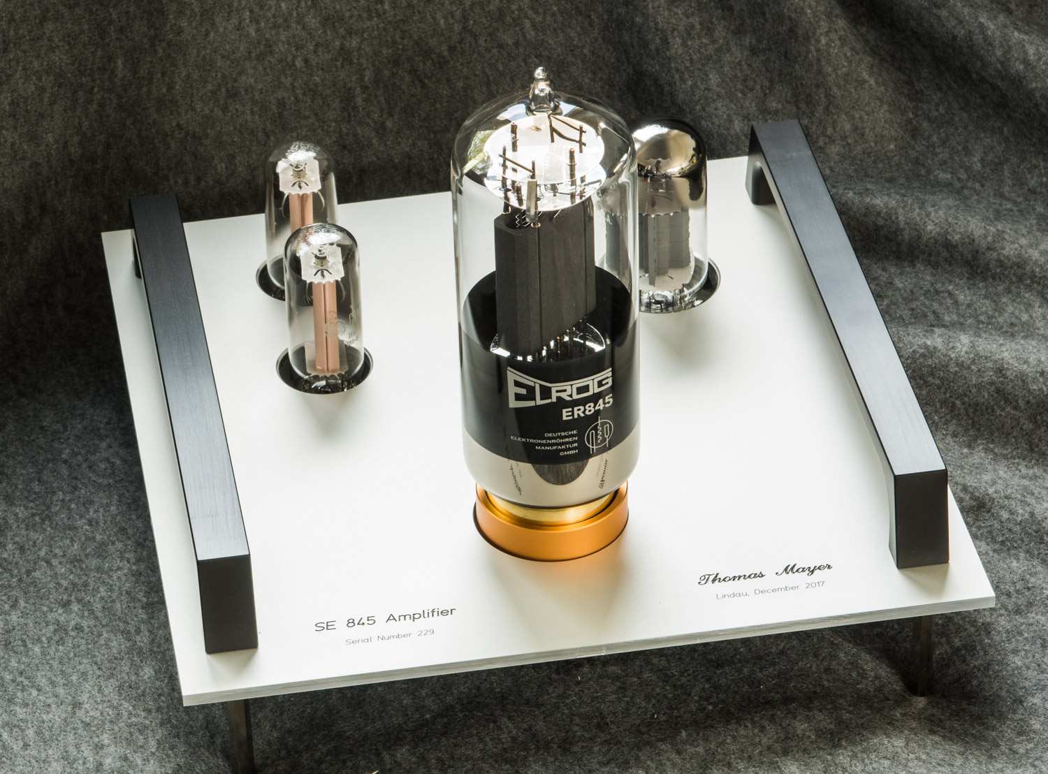
Several different 845 mono blocks are in the planning stage for the next months. Here a sneak preview how the first ones will look like.
I will start with a pair of 'entry level' monos. These will be single chassis, one per channel. So the power supply is integrated. Driver tube is the 6HS5. A pair of 6CG3 TV damper tubes will take care of the rectification. All the tubes are placed on top of the chassis without anything else:
The chassis will be tower style, about 40cm high (plus feet and tubes). The same size as the chassis used in the 300B differential amps. This is a view from the top:
All the internal parts will be mounted on several stacked sub assemblies. This are all the metal plates for the internal construction of one amp:
Stay tuned for updates as the construction of these amps progresses and other more advanced 845 amplifiers will enter the planning stage. There are some cool things coming with a unique new driver stage for 845 tubes.
Best regards
Thomas
DISCLAIMER
All rights of photos and text reserved. Usage of photos or text from my blog on other websites or for any other purpose only with prior permission. If you want to use any material from my blog please contact me by email.
Showing posts with label 6HS5. Show all posts
Friday, October 13, 2017
Wednesday, November 4, 2015
211 -The Next Generation- Part 15 : 6HS5/211 finished
Hi!
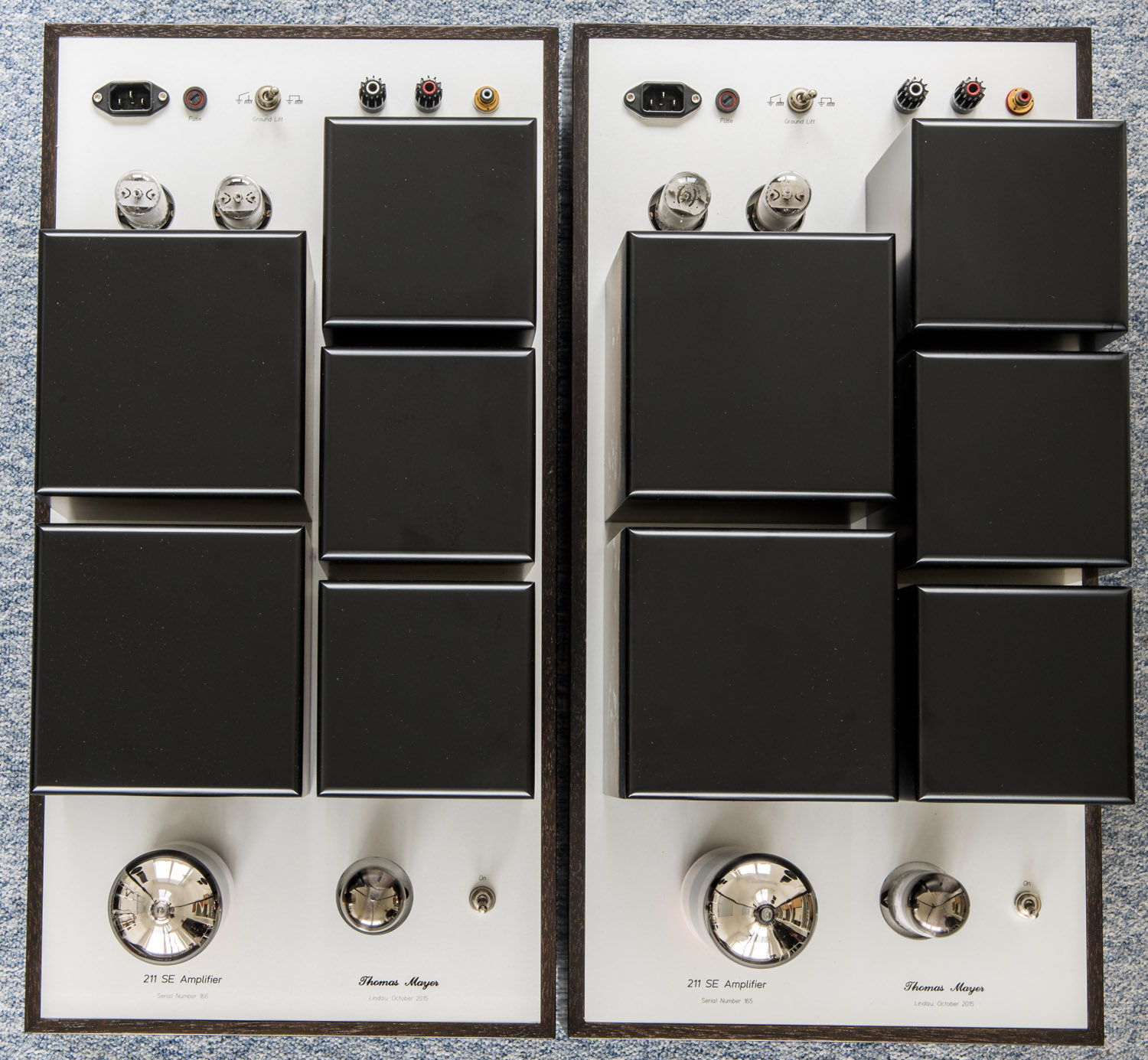
Finally here are photos of the finished 211 mono amplifiers with 6HS5 driver.
The development of the layout and the assembly have been shown in previous posts. This is how the finished amp looks like:
Finally here are photos of the finished 211 mono amplifiers with 6HS5 driver.
The development of the layout and the assembly have been shown in previous posts. This is how the finished amp looks like:
The dimensions are: 320mm wide by 620mm deep. The wooden body is 125mm high. Overall height about 310mm. Quite some boat anchors!
Both amps side by side:
First I was a bit sceptical if the design with the many transformer covers on top would work. But as it was finished, I liked it a lot.
View from the top:
The sockets of the driver and rectifier tubes are mounted a bit recessed below the main plate to provide a good clearance distance for the high voltages.
The amplifiers in operation:
Glowing in the dark:
Close up to 211 and 6HS5:
The rectifiers:
Best regards
Thomas
Wednesday, October 28, 2015
211 -The Next Generation- Part 14 : 6HS5/211 assembly
Hi!
In Part 13 of the series of posts about my next generation line of 211 amps I showed how the layout of the refreshed 211 mono blocks with 6HS5 driver is going to look like. This post will illustrate the assembly process.
Contrary to the 801A/211 amplifiers this one has the amplifier section and power supply on one chassis. This means a lot of iron needs to be fitted in.
Everything is mounted on a single metal plate:
Here the sockets, connectors and switches are already fitted. The underside:
The interstage transformer is the only piece of iron which is placed inside. Many rails and bolts are needed to hold the capacitors which will all be inside:
For the further assembly steps the plate is fixed in a rig which makes it easier to handle:
Here all the chokes and transformers are already mounted on the top side:
The inside with some initial wiring before the capacitors go in:
The amp can be tested in the assembly rig, before the transformer covers and enclosure are added. 5 covers are needed to hide these heaps of iron:
Stay tuned for photos of the finished amps!
Best regards
Thomas
In Part 13 of the series of posts about my next generation line of 211 amps I showed how the layout of the refreshed 211 mono blocks with 6HS5 driver is going to look like. This post will illustrate the assembly process.
Contrary to the 801A/211 amplifiers this one has the amplifier section and power supply on one chassis. This means a lot of iron needs to be fitted in.
Everything is mounted on a single metal plate:
Here the sockets, connectors and switches are already fitted. The underside:
The interstage transformer is the only piece of iron which is placed inside. Many rails and bolts are needed to hold the capacitors which will all be inside:
For the further assembly steps the plate is fixed in a rig which makes it easier to handle:
Here all the chokes and transformers are already mounted on the top side:
The inside with some initial wiring before the capacitors go in:
Everything in place and wired up, ready for testing:
The amp can be tested in the assembly rig, before the transformer covers and enclosure are added. 5 covers are needed to hide these heaps of iron:
Stay tuned for photos of the finished amps!
Best regards
Thomas
Sunday, October 18, 2015
211 -The Next Generation- Part 13 : 6HS5/211, Layout
Hi!
Not only the 211/211 and 801A/211 amps got a fresh design, also the 211 mono blocks with 6HS5 driver are being redone.
The 211 mono blocks with 6HS5 driver are currently my entry level version in terms of 211 amplification. Although the design of the previous version received a lot of praise, I need to redo it since I am running out of stock of the capacitors used. The capacitors were mounted on the top of the amp and were a major part of the visual look of the amps.
The new version uses the caps shown above. This is a mix of caps which are not easily arranged on the top of the amplifier chassis. So instead I decided to place almost all the transformers on chokes on the top and move the caps inside. This heap of iron needs to find a space on the amps:
All the iron will be placed under transformer covers. Two large covers are needed for the main power transformer and for the output transformer. The rest can be placed under 120mm covers. This is the arrangement I came up with:
The 120mm covers are now also available in a version which is higher, just as high as the 150mm covers, so a uniform look can be achieved if they are combined.
The metal pate for this has been designed already:
The two small plates are for the mounting of the sockets of the 6HS5 driver and 6CG3 rectifiers. The assembly of the amp will be shown in an upcoming post. Stay tuned!
Best regards
Thomas
Not only the 211/211 and 801A/211 amps got a fresh design, also the 211 mono blocks with 6HS5 driver are being redone.
The 211 mono blocks with 6HS5 driver are currently my entry level version in terms of 211 amplification. Although the design of the previous version received a lot of praise, I need to redo it since I am running out of stock of the capacitors used. The capacitors were mounted on the top of the amp and were a major part of the visual look of the amps.
The new version uses the caps shown above. This is a mix of caps which are not easily arranged on the top of the amplifier chassis. So instead I decided to place almost all the transformers on chokes on the top and move the caps inside. This heap of iron needs to find a space on the amps:
All the iron will be placed under transformer covers. Two large covers are needed for the main power transformer and for the output transformer. The rest can be placed under 120mm covers. This is the arrangement I came up with:
The 120mm covers are now also available in a version which is higher, just as high as the 150mm covers, so a uniform look can be achieved if they are combined.
The metal pate for this has been designed already:
The two small plates are for the mounting of the sockets of the 6HS5 driver and 6CG3 rectifiers. The assembly of the amp will be shown in an upcoming post. Stay tuned!
Best regards
Thomas
Wednesday, June 19, 2013
Tube of the Month : The 6HV5A
Hi!
This months tube is one of the very last developments of the vacuum tube era. A tube which was made for the regulation of the high voltage in color TVs. The 6HV5A.
The 6HV5A is a beam triode. It is very similar to the 6HS5 which was already presented in the tube of the month series almost two years ago. Pinout and most of the technical parameters are the same between these two tubes. So I won't repeat all the technical details.
The 6HV5A has a slightly higher max. plate dissipation which brings the drawback of also higher heater current. It is physically a bit larger to allow the 5W extra dissipation. A comparison between Sylvania 6HS5 and 6HV5A:
Since also the usage of this type of tubes was extensively covered in the 6HS5 article, I will not repeat that but rather allow a closer look to the construction of the tube.
The base:
During the manufacturing process the tube got evacuated through the little glass stem at the bottom:
Removing the glass to get a better view of the construction details:
The heater wire entering the cathode sleeve:
The heater wire ends are welded to the pins:
The heater wire partly removed from the cathode:
A close up of the heater :
Heater completely removed:
The plate, removed from the rest:
The beam plate, grid and cathode assembly:
This photo gives already a hint of the remarkable grid structure. A close up:
Zooming further in:
Removing the beam forming plate:
Beam plate, grid and cathode separated:
The beam forming plate:
A close up of grid and cathode ends:
Here we see how the grid wire is soldered (or welded?) to the grid rod:
View from the top side:
More details:
This tube is a fine example to show how far the vacuum tube technology was evolved before it got abandoned.
Best regards
Thomas
This months tube is one of the very last developments of the vacuum tube era. A tube which was made for the regulation of the high voltage in color TVs. The 6HV5A.
The 6HV5A is a beam triode. It is very similar to the 6HS5 which was already presented in the tube of the month series almost two years ago. Pinout and most of the technical parameters are the same between these two tubes. So I won't repeat all the technical details.
The 6HV5A has a slightly higher max. plate dissipation which brings the drawback of also higher heater current. It is physically a bit larger to allow the 5W extra dissipation. A comparison between Sylvania 6HS5 and 6HV5A:
Since also the usage of this type of tubes was extensively covered in the 6HS5 article, I will not repeat that but rather allow a closer look to the construction of the tube.
The base:
During the manufacturing process the tube got evacuated through the little glass stem at the bottom:
Removing the glass to get a better view of the construction details:
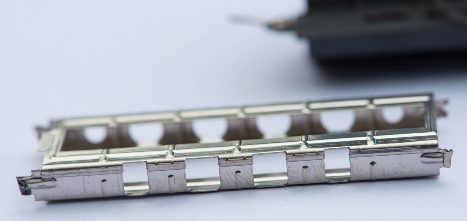
The three rings held the getter material which was flashed after evacuation of the glass bulb. The electrodes held in place by the two mica discs at either side. The beam forming plate is visible through the rectangular holes:
The heater wire entering the cathode sleeve:
The heater wire ends are welded to the pins:
The heater wire partly removed from the cathode:
A close up of the heater :
Heater completely removed:
The plate, removed from the rest:
The beam plate, grid and cathode assembly:
This photo gives already a hint of the remarkable grid structure. A close up:
Zooming further in:
Removing the beam forming plate:
Beam plate, grid and cathode separated:
The beam forming plate:
A close up of grid and cathode ends:
This photo shows the scale of the structures:
The grid pitch:
Let's have another look at the magnificent grid:
Here we see how the grid wire is soldered (or welded?) to the grid rod:
View from the top side:
More details:
This tube is a fine example to show how far the vacuum tube technology was evolved before it got abandoned.
Best regards
Thomas
Subscribe to:
Posts (Atom)