DISCLAIMER

All rights of photos and text reserved. Usage of photos or text from my blog on other websites or for any other purpose only with prior permission. If you want to use any material from my blog please contact me by email.
Showing posts with label UX201A. Show all posts

Tuesday, December 3, 2013

UX201A Sound Processor, Part 5 : Listening

Hi!

The previous 4 parts covered the circuits of signal section and power supply as well as the assembly steps for signal unit and PSU. This last post will be about the sound of this unit and it's usage.


First I'd like to explain a bit more about the purpose of this design as it might not have become very clear in the previous articles. I have been experimenting with the UX201A many years ago and found that it has a very unique sound character. It is not quite as neutral as other directly heated triodes with thoriated tungsten filaments, as the 10Y. It adds a slight bit of sweet icing on the cake.


It does this in a very subtle way, without impacting resolution much. This is not generating what many people (falsely) think 'tube sound' is. Bass response stays firm and solid (if the rest of the system is good in this respect). Treble does not get attenuated (this unit has a quite wide frequency response). The tube adds a little bit of distortion which apparently is very pleasant for the ear. It seems to enhance tone colours and can take a bit of harshness away especially from digital sources.


This can be just the right ticket if the CD-Player in the system is a bit too harsh sounding. But don't expect miracles from this unit, it cannot turn a poor sounding CD-Player into a good sounding one. The effect could also be described as putting a very tiny bit of patina to the sound. Giving it a hint of 'vintageness'. With some recordings tone colours seem to get some golden shine.


Normally my goal is to have as neutral and transparent music reproduction as possible. But since the effect of this tube is so unique, I wanted to give it another go. That's also the reason why I called it a Sound Processor. It could actually be built as a complete line stage. In fact that is how I am using it in the moment in my workshop. It drives a passive volume control unit with AVCs:


I have no analog front end yet in my workshop. I am currently using a vintage Philips CD101.


The UX201A Sound processor is just perfect to spice up the signal from this player a bit. In fact it is quite listenable and works remarkably well in this set up. Of course the system will get a proper analog front end later on. When it is complete I will post an article about my workshop system.


This unit is not meant for absolute purists. But if you have fun playing around with the sound, this is right for you. It can be simply added into an existing system, either between any source and preamp, or between preamp and power amp.


It has a high input impedance thus it is an easy load for any source. Output impedance is low so it can drive long interconnects and power amps with low input impedance. It can be used either with tube or solid state amplifiers.


The 866A mercury vapour rectifiers add the proper visual magic to the sound it produces.

If the sound descriptions above seemed a bit far fetched or 'colourful', take it with a grain of salt. This is about playing with the sound and that is very subjective and difficult to put in words.

Best regards

Thomas


Tuesday, November 19, 2013

UX201A Sound Processor, Part 4 : PSU Assembly

Hi!

In the last article about the UX201A Sound Processor I presented the power supply circuit. Now we will have a look at the assembly process of the PSU.


Since the power supply will be used along with the signal section, the chassis style should be similar, so no wooden enclosure but an all metal chassis. Same width and height, but the chassis had to be longer to fit everything in.

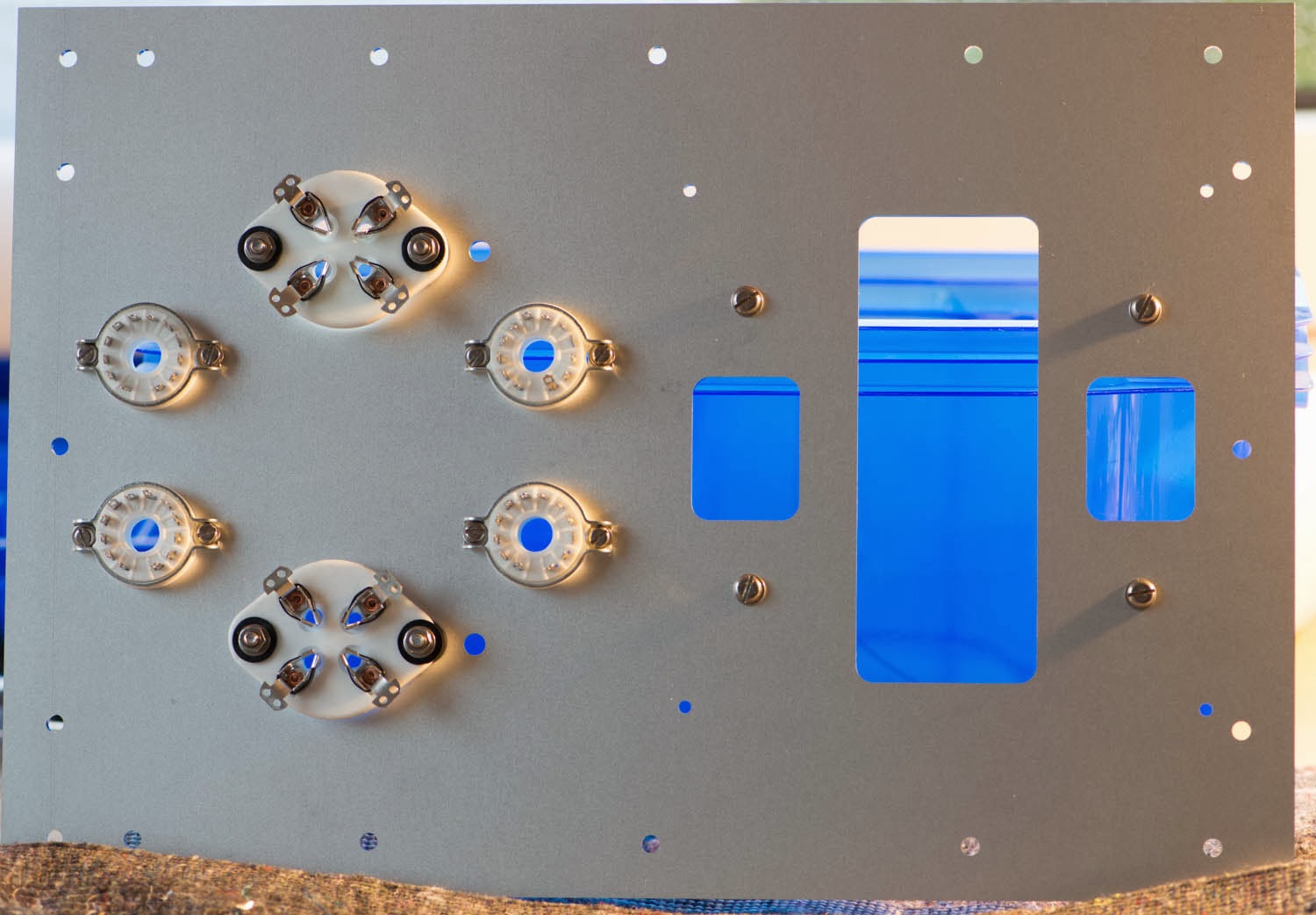
Here is a photo of the top metal plate which carries the tube sockets and the main power transformer:


The rubber damping elements around the break outs on the right will carry the power transformer. There are 4 compactron sockets for 6CG3 tubes and two UX4 sockets for 866A mercury vapour rectifiers. These will be wired such that both versions of the power supply as shown in the previous article can be used. If the 866A/6CG3 version is used, the two 6CG3 sockets in the front are simple left empty. Alternatively only the compactron sockets can be equipped with tubes to use the all vacuum tube bridge.

The underside of the top plate:


The side panels of the chassis are attached to the top plate by aluminium rails:


The back panel is attached in the same manner. Side panels and back plate are screwed together via a shorter aluminium rail:


The enclosure with all side panels, back plate and front plate:


The main power transformer sits on the top and will later be hidden under a transformer cover:


There is a separate filament transformer for the 866As: It is mounted over the tube sockets which are already wired up:


Capacitors, chokes and bleeder resistors are added and wired up. The inside of the finished PSU:


Closing the chassis with the bottom plate:


The finished PSU in operation:


More views:


The top side:


The glow of the tubes in the dark:


More blue glow :


In the next and final part about the Sound Processor I will write about it's sound effect and how it can be used. After the questions I got about it I realised I did not elaborate enough about the purpose of this device. Stay tuned for more about this.

Best regards

Thomas


Saturday, November 16, 2013

UX201A Sound Processor, Part 3 : PSU circuit

Hi!

The circuit and assembly of the UX 201A Sound Processor  have been covered in previous posts, this and the next article in this series will be about the power supply.


The power supply only has to deliver a single voltage of about 150VDC. But at a hefty current of 0.5A. So we need a power supply with some grunt. If rectification should be done with tubes, the average rectifier will not do. We need something tough which can handle this amount of current. Even among TV dampers, the choice is limited for such a high current. But there are some which can handle this job. For example the 6CG3.

I have chosen a full wave bridge rectification scheme for the task. This is the circuit:


Quite straight forward, no surprises here. Since the voltages in this power supply are rather low and the 6CG3 allows quite large voltage difference between heater an cathode all heaters could be wired in parallel and fed from a single winding, referenced to ground. But the 6CG3 draws a lot of heater current. 4 of them need almost 8A. Since the power transformer which I used has two separate 6.3V heater windings, I split the 6CG3s into two pairs which are heated from one winding. The two tubes in the middle deliver the raw B+ voltagesat their cathodes. These share one of the heater windings, which is connected to raw B+ at one end. The two other 6CG3s are fed from the other heater winding which is referenced to ground.

The rectifier is followed by a choke input filter, using two LC sections. The chokes are Lundahl LL1638 gapped for 3Hy/500mA. The caps are 220uF/350V electrolytics. A 350V rating is used so that the capacitors will not get stressed with over voltage in case the power supply is turned on without the signal section attached. In that case the output voltage will rise significantly since the current draw would drop below the critical value to ensure proper choke input operation of the filter. The 20k bleeder resistor ensures that the high voltage gets drained after turn off if no load is attached.

No worries about the use of electrolytics. Each channel is decoupled by a choke in the signal section.

So far so good, but such beautiful tubes as the UX201A deserve some similarly awesome rectifier tubes. Here is an alternative PSU circuit using the 866A mercury vapour rectifier:


Two of the 6CG3s are replaced by 866As. Since they require a different heater voltage a separate filament transformer is added which provides 2.5V. Each 866A needs 5A filament current. So it might be easier to use two separate heater windings which can provide 5A each. If a 10A filament transformer is available they can be heated in parallel as shown in the schematic. The raw B+ is derived from the center tap of the 866A filament winding. If two separate filament windings are used, their center taps need to be connected. The filter section remains the same. Due to the lower voltage drop of the 866As, the secondary voltage needs to be a bit lower.

Two 6CG3s remain in the circuit in the ground path to complete the full wave bridge. They also provide a delayed high voltage to allow pre heating of the 866As without a separate switch. This has a cool effect when turning the supply on. At turn on there is no blue glow. As the 6CG3 heat up, a faint blue glow starts to appear between filament and plate of the 866As which slowly gets brighter as the TV dampers fully warm up.


The assembly of the PSU will be shown next, stay tuned.

Best regards

Thomas


Friday, November 8, 2013

UX201A Sound Processor, Part 2 : Assembly

Hi!

After the presentation of the circuit in part 1 of the article series about the UX201A Sound Processor, this post will show the assembly steps.


Since this circuit needs massive heatsinks, the usual chassis with wooden frame would not work. So I designed a completely new full metal chassis style. The chassis was sized as compact as possible.

The top metal plate with sub plates for the tube sockets:


The sockets are mounted to sub plates which in turn get attached to the main plate by rubber damping elements as seen in my DHT preamps and phono stages.


The sub plate mounted into the main plate:


Pre assembled main plate:


Adding the Tango NP8 line output transformers. The connection between transformers and plate pins are already in place (done with solid core silver wire and additional insulation sleeve):


Preparation of the heatsinks:


The 3 resistors on the left side are 1.5k/25W types. They will be wired in parallel to get the 500 Ohm resistor through which the filament voltage is derived from B+. It has been split into three resistors to spread out the heat dissipation. The resist on the right is the 22 Ohm filament bias resistor.

Mounting the heatsinks to the top plate :


Wiring of the resistors. The main ground buss is also in place already (wire at the bottom):


Adding the chokes :


The chokes are nice nickel core units wound for me by Dave Slagle


View from the backside before the panel with the connectors is attached:


Preparation of the back panel:


There are two sets of outputs. The NP8 secondary has a tap for extra low output impedance.

Backplate attached to the Sound Processor:


Adding the bottom plate :


Finished:


In the next articles the circuit and assembly of the power supply will be covered. Stay tuned!

Best regards

Thomas