DISCLAIMER

All rights of photos and text reserved. Usage of photos or text from my blog on other websites or for any other purpose only with prior permission. If you want to use any material from my blog please contact me by email.
Showing posts with label 6CG3. Show all posts

Friday, October 13, 2017

845 Mono Amplifiers - Part 1

Hi!

Several different 845 mono blocks are in the planning stage for the next months. Here a sneak preview how the first ones will look like.


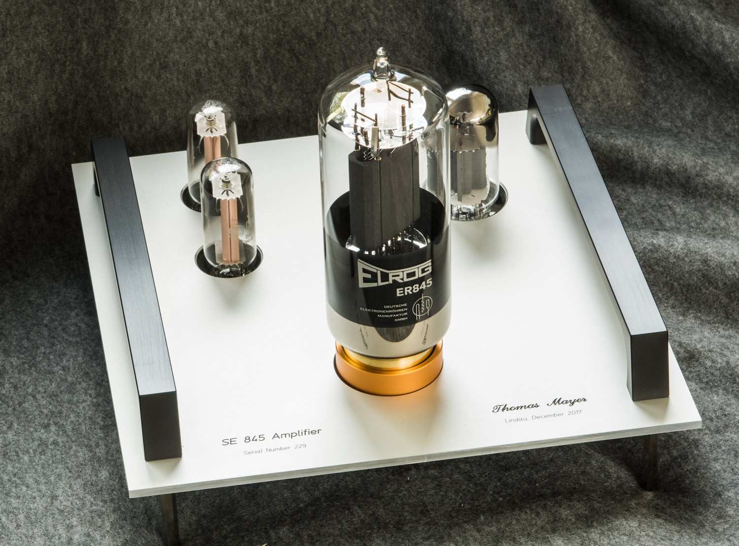
I will start with a pair of 'entry level' monos. These will be single chassis, one per channel. So the power supply is integrated. Driver tube is the 6HS5. A pair of 6CG3 TV damper tubes will take care of the rectification. All the tubes are placed on top of the chassis without anything else:


The chassis will be tower style, about 40cm high (plus feet and tubes). The same size as the chassis used in the 300B differential amps. This is a view from the top:


All the internal parts will be mounted on several stacked sub assemblies. This are all the metal plates for the internal construction of one amp:


Stay tuned for updates as the construction of these amps progresses and other more advanced 845 amplifiers will enter the planning stage. There are some cool things coming with a unique new driver stage for 845 tubes.

Best regards

Thomas


Saturday, June 6, 2015

Field Coil Power Supply with Mercury Vapour Tubes

Hi!

The mercury vapour madness continues. Here is a power supply for RCA 1443 midrange drivers. It uses 816 mercury vapour rectifiers in a bridge rectification arrangement with two 6CG3 TV Dampers.


The RCA1443 has a high voltage field coil which requires 115 VDC at 170mA current. This spec makes a tube rectified supply feasible. Especially when the drivers for left and right are fed in series, then the voltage doubles to 230V.


Smoothing of the voltage is done in a purely passive fashion using chokes and oil caps.


Digital displays have been added to monitor voltage and current.


Output voltage can be adjusted in several steps to account for variations in line voltage and actual current draw from the drivers.


With a current of 170mA the blue glow of the 816 tubes is clearly visible at daylight:


And becomes more visible in the evening ...


... or at night


The 6CG3 tubes provide a nice slow warm up as can be seen in this video clip:


Here seen from another angle:


Best regards

Thomas


Thursday, February 20, 2014

211 Drives 211, Part 4

Hi!

First sounds from one channel of the 211/211 amplifier!


After the first amplifier section was finished, I did the assembly of it's power supply unit which is built in the same circular style, with several round plates carrying submodules. Starting from the bottom, the first one holds the main power transformer for the high voltage and the connectors for umbilicals and mains, which plug in from the bottom:


A set of bleeder resistors is mounted on the same sub assembly:


The next level holds the filament transformers and chokes:


The rectifier bridges for the filament voltages are mounted on solder terminals in the middle, stacked on top of each other:


Then the smoothing caps for the filaments:


The two resistors on top of the stack are bleeder resistors to ensure the filament chokes will carry critical current for proper choke input operation even when the amplifier is disconnected from the PSU.


Chokes and large paper in oil caps for the smoothing of the high voltage supplies for output tube and driver:


And finally the top plate which holds the sockets for the rectifier tubes:


Rectification is done with a full wave bridge which can either consist of a pair of mercury vapour 866A, supplemented by a pair of 6CG3 TV dampers, or alternatively a bridge of 4 6CG3s.


The completed power supply:


View from the top:


The blue glow of the mercury rectifiers:


First test of the amp with the PSU, here with 836 instead of 866As:


The capacitors lying on top of the amp is a last minute tweak. The amp is playing nicely, tweaking is finished and the assembly of the second channel can start. Different versions for the housing are also in preparation. Stay tuned!

Best regards

Thomas


Friday, November 29, 2013

Tube of the Month : The 6CJ3

Hi!

In the power supply for the recently presented UX-201-A circuit, I am using 866A mercury rectifiers along with 6CG3 TV damper tubes. In this months tube article I would like to present a suitable alternative, The 6CJ3.


JC Morrison was an early advocate of the use of TV dampers as rectifiers and also used the 6CJ3 in some projects which got presented in the famous Sound Practices magazine in the 1990ies.


For all technical parameters please see the General Electric data sheet. The 6CJ3 mainly differs in the base from the 6CG3. While the latter has a 12-pin compactron base, the 6CJ3 is a 9-pin Novar tube. The pinout is shown on the left. The Novar base is not to be confused with the Noval base which is also called miniature base. On the Novar base the pins are placed along a circle with a larger diameter. To make the confusion complete there is another 9-pin base called Magnoval.
Novar and Magnoval bases are very similar, they only differ in the diameter of the pins. The Magnoval pins are a bit thicker. This means a 6CJ3 would slip easily into a Magnoval socket but would not get good contact. As mentioned the 6CJ3 is electrically very close to the 6CG3. They have the same heater voltage and current and similar peak inverse voltage ratings and they can deliver similar currents. They also look very much the same. Several times I tried to shove a 6CJ3 into the rectifier socket of an amp which was configured for 6CG3. Only realising after several attempts that somehow the number of pins did not match the number of holes in the socket. There had been a lot of TV damper types which were actually very close electrically. Probably the tube manufacturers wanted to have their own types for certain applications. More about that later on.

Here is a photo showing the 6CJ3 in comparison to the 6CG3:


Very similar in size, shape and internal construction. Only different bases:


And here a photo showing the difference between the Novar base of the 6CG3 and a Magnoval base, in this case of a EY500, a tube which will be covered in a future article:


The Novar is on the left and Magnoval on the right. Very easy to mix up, only a close look reveals the difference in pin diameter:


And finally a comparison between the Novar and Noval bases:


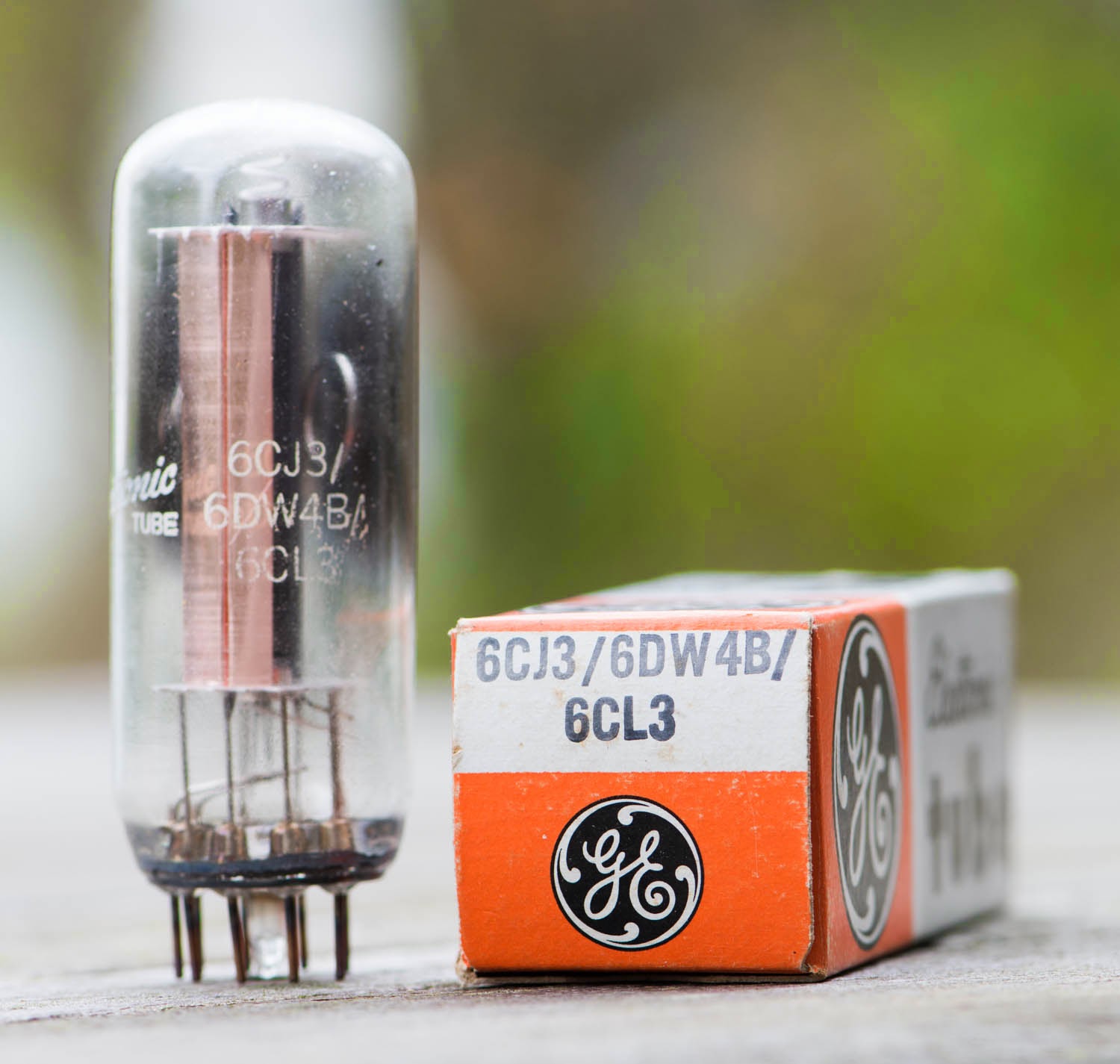
As mentioned above there had been an outburst of TV damper type registrations from different manufacturers for almost the same tubes. Later on it became common practice to print several type designations on tubes to cover that manifold of numbers with just a few tubes. For example like this:


This tube bears three type designations: 6CJ3, 6DW4B and 6CH3. Interestingly these types are close electrically but not identical. For example the 6DW4B data sheet specifies a significantly lower heater current of 1.2A versus the 1.8A of the 6CJ3. Also the current and voltage ratings differ a bit. While this might be ok for most applications it can become critical if a circuit relies on the exact values of a type.

Here is another example:


If you have any of these tubes with multiple type designations, best practice would be to assume the worst case ratings and make sure the circuit will work with them.


Now let's have a closer look at the construction of this tube.


Removing the glass:


The plate with the ring attached which held the getter:


Connections between electrodes and base pins:


This spiral ensures isolation between heater wire and cathode:


Heater and isolation spiral removed from the cathode:


The cathode:


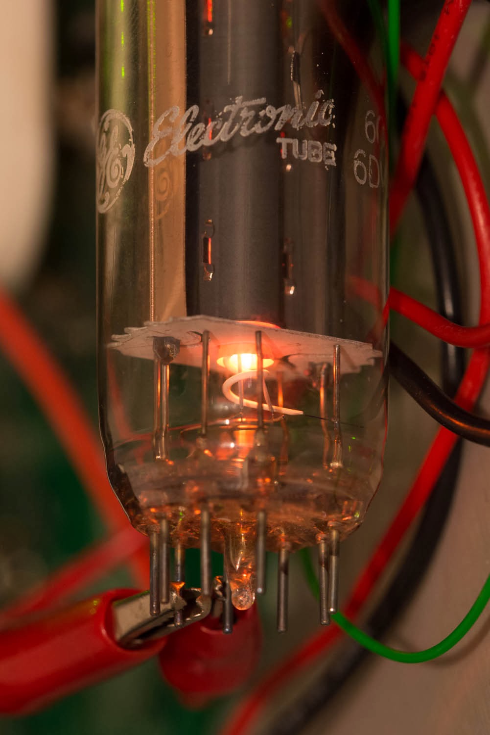
And finally a few photos of the 6CJ3 lit up:


In the dark:


Close up:


The top:


Close up:


Best regards

Thomas