
In the first part of the series of articles about this amp the schematic was shown and explained. The second part showed all the components used. Today we will see the first steps of the construction.

The photo above shows all the components and the tools needed. Let's start with the mounting of the tube sockets. For these we use two 4mm screws.

Since the screw head is visible from the top, a type with a head for hexagonal allen keys is used. To avoid direct contact between the ceramic socket and the metal plate a rubber ring is placed in between:
Then the socket is added with two more rubber rings before the nuts are screwed on:

The socket fully mounted:

All 3 sockets mounted into their holes:

Next we take care of the RCA connector for the signal input:

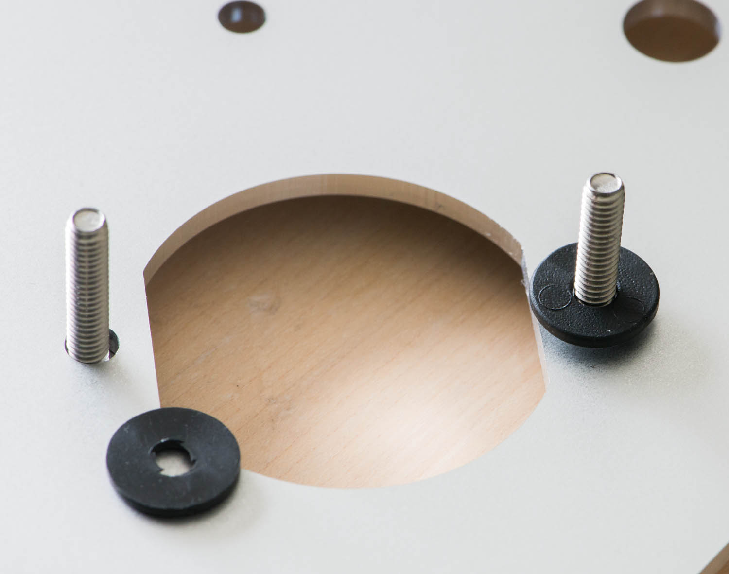
The connector comes with two plastic isolation rings, a ring for the ground connection and two screws for mounting.
 One of the plastic rings has a little collar. It is the one which is already stuck onto the connector in the photo above. This one stays on the connector when it is inserted into the plate, so it's visible from the outside. The hole in the plate needs to be big enough so that this collar extends into it. This way it is ensured that the RCA connector is isolated from the metal plate which is important to avoid ground loops. Then the second plastic ring is put on. This ring isolates the connector from the under side of the plate. Then everything gets tightened to the plate with the first of the two screws. The ring for the ground connection is placed between the two screws.
It is important that the screws are secured very tight to avoid that the connector loosens over time. Many people have the habit of twisting the connector when they insert or remove the interconnect. This can loosen the screws over time. To make sure the screws stay in their place after they are tightened, they are secured with some solder. This should be applied such that it covers the ground part of the connector, the screw and the ground ring. This way it will stay in place even if the cable is twisted a bit and a secure ground connection is made. Be careful to not shorten out the ground part with the inner pin for the hot side of the signal.

Then we add the banana sockets for the speaker terminal:

The fuse holder:

Next the switches for ground lift and mains on/ff. These are screwed on with a ring from the top:

For the mains connection, a IES socket with integrated filter is used:

It attaches to the plate with two 3mm screws:

Next the rubber dampers which are mounted on top of the plate and which will later carry the power transformer:

T secure their connection some varnish is applied. It makes sense to use that on every metal screw. This avoids that they get loos over time or if the amp is transported or shipped.

The preassembled metal plate:


Now the power transformer is added:
A close up showing how the transformer rests on the rubber damper:

Before more parts get mounted on terminal strips, some initial wiring should be done since things get crowded later on. I usually start with the mains wiring:


The mains is connected to the primary side of the power transformer:

Next the heater. The 6N7 driver and 6CB5A output tube share one heater winding, while the 6BY5GA rectifier gets it's own. This is done because the rectifier heater is connected to B+ to avoid large hetaer to cathode voltage differences. The heater of the signal tubes will be referenced to ground via two 100 Ohm resistors later on

The single black wire coming from the transformer is connected to the screen between primary and secondary windings. This will later be connected to signal ground.

The only connection to the power transformer which remains to be done is the high voltage to the rectifier:

Each of the two wires has it's own protection sleeve due to the high voltage. Like the other AC carrying wires they get twisted together and connected to the plate pins of the rectifier socket.

In the photo above the two cathodes of the rectifier are connected together and to one side of the heater. On the signal tube sockets some pins which are connected in parallel are tied together with a short piece of wire inside some insulation sleeve.
The rest of the assembly process will be covered in part 4. Stay tuned!
Best regards
Thomas
Fantastisch beschrieben - danke
ReplyDeleteHallo herr mayer
ReplyDeleteWieviel würden die netztrafos bei ihnen kosten?
Grüsse hannes schrotter
Hallo!
ReplyDeleteDie Netztrafos sind sehr hochwertig mit kornorientierten Blechen und doppelter Schirmung zwischen Primär- und Sekundärseite. Diese setze ich auch in meinen aufwändigeren Verstärkern ein. Diese kommen auf 125,- pro Stück.
Auch Drossel und Ausgangsbertrager können von mir bezogen werden. Ich bin per email erreichbar: thomas -at- vinylsavor -punkt- de
Viele Grüße
Thomas
Nice post.
ReplyDeleteA valuable information here.
Thanks for sharing with us.
Automatic Voltage Regulators
Hallo herr mayer
ReplyDeleteIch hätte noch 2 trafos aus einem nie gebauten projekt.
Sekundär1 330volt 5A und seundär2 6,3volt 5A.
Würden die auch gehen?
So würd ich mir wenigstens einen neukauf der netztrafos sparen.
Grüsse
Hannes
Hallo Hannes,
ReplyDeletedie würden gerade so gehen. Die etwas geringere Hochspannung macht nichts, gibt etwas weniger Ausgangsleistung. Etwas problematischer ist die einzelne Heizwicklung. Man müsste sowohl die Signalröhren als auch den Gleichrichter an die gleiche Wicklung hängen. Die würde ich dann nicht auf Massepotential legen sondern mittels Spannungsteiler auf ca +50V. Dann bleibt die Ufk der 6BY5 gerade so im Limit. Nicht ganz so elegant würde aber gehen. Mit Vollsilizium-Gleichrichterbrücke statt der 6BY5 wäre es allerdings kein Problem mehr
Viele Grüße
Thomas
Hallo thomas
ReplyDeleteDanke für die antwort.
Ich würde sowieso mit dioden bauen.
Ich möchte einmal eine resteverwertung durchführen und hab auch schon alles zuhause bis auf die röhren.
Wenns gefällt werde ich auf jedenfall auf eine höherwertige version sparen.
Danke nochmal für die infos
Grüsse hannes
Hallo Hannes,
ReplyDeletedann kannst Du den Trafo problemlos verwenden! Falls Du Interesse an Ausgangsübertrager oder Drossel hast, melde Dich bei mir. Die gibt es zu guten Preisen.
Gruß
Thomas