
All the previous posts in this series showed indirectly heated tubes in the output stage. Today we will see how the same concept can be applied to directly heated tubes as well:
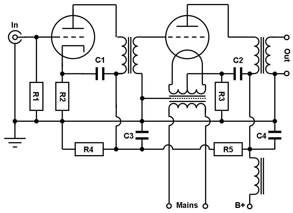
This is a generic schematic which shows how this can be adapted to DHTs like 45, 2A3, 300B, etc. The driver stage can stay the same as in the 6CB5A version. The main point which is different is the cathode of the output tube which is now directly heated, that means the filament itself becomes the cathode and thus is in the signal path. So it needs to be handled with some care. DHTs can be heated with AC or with DC. The schematic shows AC heating which is the simplest form and can easily be done such that the filament supply has no negative impact on the sound. This is much more difficult in the case of DC heating and will be covered in a later post.
AC heated DHTs have one draw back: There will be some remaining hum. Often hum bucking pots are seen in these cases. However we want to avoid such an ugly pot right in the signal path. This requires a filament transformer which has center tapped windings. This center tap becomes the cathode connection of the tube and is hooked up to the cathode bias resistor. It is also the connection point for the ultrapath capacitor (C2).
This method does not allow any hum adjustment and relies on symmetry of the filament winding and the filament itself. Hum level can vary a bit from tube to tube. Very well suited for this scheme are the 2.5V filament types like the 45 or 2A3. Residual hum will be negligible with these. With 300Bs, hum level could become too much with this scheme as they are heated with 5V. I personally prefer DC heating for 300Bs for this reason. With 45s and 2A3s I stick to the AC scheme as pictured.
As mentioned already, the filament supply is very critical. Any noise present here will be injected into the signal. For this reason the filament transformer should be of high quality and have a screen between primary and secondary sides. As usual I even use transformers with two screens. The filaments should be supplied from a separate transformer. The filament windings should not be on the same core as the B+ windings. This avoids any switching noise from the B+ rectifier to be injected into the filament circuit. In a stereo amp, both windings for the two channels can be on the same transformer. Even if the power supply of the amp is separated into an external chassis, the filament transformer for the output tubes should stay in the amplifier section, close to the output tubes.
The rest of the schematic is the same as shown in previous posts. The interstage transformer needs to fit to the driver tube. Again the 6N7 works nicely with a LL1660/10mA driving small DHTs like 45 or 2A3. For the 300B it is advisable to use the beefier 6J5 instead of the 6N7. The output transformer also needs to be matched to the tube used. For example a Tango XE20S, configured for 5k primary for the 45. Also the Lundahl LL1663 would work nicely.
C1 and C2 are the ultrapath capacitors as has been described in previous posts. C3 is the B+ decoupling cap of the driver stage. C4 decouples the output stage separately for each channel. R1 is the grid to ground resistor of the input tube and also sets the input impedance of the amp. Values of 100kOhm or 200kOhm are suitable. R2 is the cathode resistor of the input tube which sets it's operating point. In case of the 6N7, 1kOhm is a good value. A 1W rating is sufficient here. R3 is the cathode bias resistor of the output tube. In case of the 45 1.5kOhm/5W would be suitable. It needs to be chosen correctly for other DHTs. In both cases trials with and without cathode bypass capacitors can be made. Depending on the plate resistance of the tubes and the size of the ultrapath cap, a bypass cap can be necessary to avoid early low frequency roll off. A good starting point would be 25-30uF for all the caps shown in the schematic.
The choke decouples the two channels from each other and from the power supply which can be common to both. The current rating of the choke needs to be sufficient, depending on the current draw of the tubes. R5 decouples the driver B+ from the output tube. It needs to be set according to tube choice. R4 forms a voltage divider with R5 and also acts as a bleeder resistor. B+ and the value of these resistors depends on the voltage requirement of the tube chosen. For example a 45 would require around 300V B+.
Of course the same RC coupled driver stage which was shown as a lower cost alternative in an earlier post, can be used with a DHT as well. The same type power supply as shown before can be used. The voltages need to be adapted accordingly.

The photo above shows a 45 amp with external PSU based on this concept. The amp is equipped with globe UX245 tubes. The next photo shows another implementation. This one can accept both 45 or 2A3s as output tubes. The correct operating point for each is chosen by a switch which seloects the appropriate cathode resistance:

In future installments of this series we will see how this concept looks like with DC heated filaments and how this can be modified for an all directly heated amp with tubes like 26 or 10Y in the driver stage.
Best regards
Thomas
Hi Thomas,
ReplyDeleteGreat post, as always. Is there ever an indication for an input transformer, other than for step-up purposes, in your amplifiers? I know your preamplifiers all provide low impedance transformer coupled output.
Regards,
Matt
Hi Matt,
ReplyDeleteI usually use input transformer with step up if I need the addional gain. For example the 45 amp with 26 driver can be optionally equipped with input tranformer since it has very low gain without.
Custom build are usually build without input transformer since they need adequate preamps to drive them with low Zout. On request and if it matches to the system I use input transformers. Most amps which I use in my own system have them.
Best regards ... Thomas
I know it's been a long time since this post, but I'd be really interested to learn more about the DHT driver stages. Any chance you could revisit the series?
ReplyDeleteHello,
ReplyDeleteI know this past was made a few years ago but I couldn't help but be curious about the DHT driver stage. Any chance of a revisit to the series? I'm very interested in building this amp.
-Yann
Hi!
DeleteThis concept was meant to show how to build excellent sounding amps at modest cost. A DHT driver will increase the cost dramatically since it needs a very well filtered DC filament supply and either a third stage or input transformer to get enough gain. The latter in turn requires a suitable preamp to be driven adequately. I do sell kits for amps with DHT drivers. These kits include the schematics and technical details.
Best regards
Thomas
I see your point. I don't think I could even afford a pair of 10Y on top of a 45. I guess when you mentioned the possibility of using DHTs as drivers my curiosity was piqued. It's such an interesting set of articles and I wanted to read more.
DeleteMay I ask, you mentioned the interstage transformer gives more headroom, how does it do that if the ratio is 1:1?
Also, if I were to build the amp with the 6CB5A would I be able to get away with a buffer preamp if my speakers are 114db sensitive?
Hi!
DeleteA resistor as plate load would eat up half of the supply voltage. That's why the IT gives more potential headroom at the same given B+
Regarding the other question, you need to calculate the total gain and check with your source levels if that would be sufficient (most likely is, but I don't know your sources)
Thomas,
ReplyDeleteI've just finished building your 866/6ax4 PS, now on to the amps. . . .
I'd like to run your concept schematic above for 300b with DC filament & interstage transformer from the 6j5 driver. I have a rod coleman heater setup and nice parafeed chokes and OPT's from magnequest that I'd like to reuse from a previous project. I don't really see how to reconfigure the concept for parafeed, it it possible?
thanks so much,
David