DISCLAIMER

All rights of photos and text reserved. Usage of photos or text from my blog on other websites or for any other purpose only with prior permission. If you want to use any material from my blog please contact me by email.
Showing posts with label 841. Show all posts

Thursday, January 3, 2013

Die direkt geheizte Kette

Hi!

I received several requests to translate the report about the DHT amplification chain to German. So here it is:

Hallo!

Auf Wunsch hier eine Übersetzung des Artikels über das Hören mit der durchgehend mit direkt geheizten Röhren aufgebauten Kette.


Über die Feiertage konnte ich mich ausgiebig mit der direkt geheizten Verstärkerstufe beschäftigen und möchte einige Eindrücke wiedergeben.

Als ersten Test wurde die Ausgangsstufe des E55L LCR Phonovorverstärkers welcher in den letzten Monaten hauptsächlich in meiner Kette in Gebrauch war, gegen die 841/801-Stufe getauscht. Die E55L Phonoeingangstufe verblieb zunächst am Beginn der Kette. Von dieser in einen 600 Ohm LCR Entzerrer, basierend auf den Tango EQ600P Modulen. Vom Entzerrer direkt in die 841/801 Stufe. Da diese genügend Verstärkung hat, ohne Step-Up-Übertrager nach dem Entzerrer. Dann in die 6AH4 Hochpegelstufe, welche wiederum einen 10Y/45 Endverstärker ansteuert.

Das war so zwar ein etwas ungewöhnlicher Mix aus direkt und indirekt geheizten Röhren, verschaffte aber einen guten ersten Eindruck über die Eignung von 841 und 801 Röhren im Phonobereich. Insbesondere Mikrophonie ist bei direkt geheizten Röhren kritisch bei solch kleinen Signalpegeln. Das war in dieser Konfiguration allerdings überhaupt kein Thema, dank der vibrationsdämpfend gelagerten Röhrensockel. Auch Brumm und Rauschen auf erfreulich niedrigem Niveau. Der erste Klangeindruck war hervorragend. Sehr weich und doch detailreich.

Aber die eigentliche Frage war ja, wie würden sich solche direkt geheizten Trioden in einer Phonoeingangsstufe schlagen? Sind sie da noch praktikabel einsetzbar, oder wird das ganze durch Mikrophonie und zu hohes Rauschen nicht mehr verwendbar? Es ging ja auch darum die komplette Verstärkerkette mit direkt geheizten Röhren zu haben. Also kam als nächstes die 10Y Hochpegelstufe zum Einsatz.


Das Resultat war grandios. Keine übermässige Mikrophonie. Brumm und Rauschen auf absolut akzeptablem Niveau. Natürlich ist ein Klingeln im Lautsprecher zu hören, wenn man die Eingangsröhren antippt. Rauschen und Restbrumm auch nicht auf solch niedrigem Niveau, wie es z.B. mit EC8020 oder E55L erzielbar ist, aber absolut im Rahmen.

Dies ist nun eine komplett direkt geheizte Kette. Vom Abtaster geht es über Lundahl LL1933Ag Silber-MC-Übertrager, verdrahtet 1:16, an die Gitter der 841. Diese ist DC-gekoppelt an eine 801 von welcher das Signal mittels Ausgangsübertrager mit Untersetzung niederohmig an den LCR Entzerrer gegeben wird. Vom 600-Ohm Entzerrer geht es dann direkt in einen der Übertragereingänge der 10Y Linestufe. Diese hat neben zwei herkömmlichen Hochpegeleingänge zwei Übertragereingänge, wahlweise mit 1:4 (12dB) oder 1:11,2 (ca 21dB) für zusätzliche Verstärkung. So kommt das ganze ohne weitere Stufe nach dem Entzerrer aus. Die Linestufe hat einen Ausgangsübertrager von Tribute, dessen Sekundärwicklung mittels wählbarer Abgriffe als Lautstärkesteller fungiert. Die Linestufe steuert wiederum eine Endstufe mit der 45 Triode an, welche von einer 10Y angetrieben wird. Die Endstufe verfügt wiederum über einen 1:4 Eingangsübertrager. Also durchgehen direkt geheizte Röhren. 4 Stufen davon mit thorierten Wolframfäden.

Hier die Endstufe:


Wie klingt es nun? Jeder der schonmal den Unterschied zwischen direkt geheizten und indirekt geheizten Röhren erfahren konnte, kann sich eine Vorstellung vom resultierenden Klang machen. Extrem detailreich, ohne auch nur ansatzweise nervend zu werden oder ins kühl-analytische abzugleiten. Dabei sehr weich und musikalisch. Stellenweise eine nahezu beängstigende Lebhaftigkeit.

Dieser erste Test wurde mit gewöhnlichen Röhren gemacht. Alle mit Metallanoden und dem sogenannten ST-Kolben. Hytron VT51 und Taylor VT62, jeweils Militärversionen der 841 respektive 801A

In Hochpegelstufen hatte ich immer sehr gute Erfahrungen mit 801 mit Graphitanoden und Keramicksockeln gemacht. Diese zeichneten sich immer durch geringe Mikrophonie aus. Da ich auch 841 in dieser Konstruktionsart habe, war ich natürlich gespannt wie diese spielen werden. Die sollten dann gerade für die Phonostufe prädestiniert sein. Überraschenderweise zeigten diese sich aber als empfindlicher gegenüber den Hytrons. Immer noch brauchbar, aber deutlich mikrophonischer. Allerdings habe ich bisher nicht viele Exemplare durchprobiert.

Wie würden sich glimmerfreie Ballonröhren schlagen?


Meine Favoriten! Auch hier Mikrophonie in beherrschbarem Rahmen. Super hochauflösend. Unglaublich schöne Stimmen. Teilweise fast schon unwirklicher Klang.

Macht diese Phonostufe nun die anderen mit indirekt geheizten Röhren überflüssig? Nein, sicher nicht. Eine sauber implementierte LCR-Phonostufe mit indirekt geheizten Röhren spielt schon auf extrem hohem Niveau. Die direkt geheizte Variante ist etwas für Liebhaber, die dem speziellen Klang solcher Trioden nachjagen. Eine Lösung mit indirekt geheizten Röhren ist praxistauglicher und vielseitiger einsetzbar. Obwohl die Mikrophonie beherrschabar ist, muss man mit Aufstellung mit unter etwas experimentieren. Eine solche Vorstufe wird auch wartungsintensiver sein. Jedes kleine Problem an den Röhren oder verschmutzte Kontakte können schnell mal zu Störgeräuschen führen.


Die Gesamtverstärkung dieser Kette ist minimal, gerade noch so praktikabel. Mit extrem leisen Abtastern, oder Endstufen mit geringer Eingangsempfindlichkeit könnte die Verstärkung zu wenig sein, wenn eine Platte mal mit geringerem Pegel aufgenommen ist, oder man generell mit hoher Lautstärke hören möchte. Für meine Hörgewohnheiten allerdings absolut ausreichend. Ich konnte sogar auf den Übertragereingang an der Linestufe mit dem niedrigeren Übersetzungsverhältnis gehen. Der Lautstärkesteller war dabei allerdings immer schon ins obere Viertel aufgedreht.

Gegenüber dem ersten Aufbau haben die Netzteile eine kleine Veränderung bekommen. Holzabdeckungen für die Netztrafos, statt Metallhauben.

Die Hochspannunsgversorgung:


Das Netzteil für die Heizung:


Viele Grüße

Thomas


Tuesday, December 25, 2012

Listening to the all DHT amplification chain

Hi!

I have been extensively experimenting with the DHT gain stage in the recent days and would like to share some listening impressions.


As an initial test it replaced the output section of the E55L LCR phono stage which I've been using recently. The E55L input stage feeding the 600 Ohm LCR RIAA EQ, from there straight into the DHT gain stage. Since it has quite a lot of gain, no step up transformer at the input of the DHT stage. From there into the 6AH4 line stage and then into a 10Y/45 power amp.

Although this was a strange mix of IDHTs and DHTs it gave a good first impression about the suitability of the 841 and 801 in a phonostage. Microphonics were surprisingly low due to the use of vibration damped tube sockets. Noise and hum also very low. Initial sound impressions were excellent. Very smooth and detailed.

But the real question was, would this DHT gain stage also be usable at the input side of the phono, enabling an all DHT amplification? Or would noise and microphonics render it impractical? I hauled the 10Y linestage up from the basement. To give an all DHT amplification chain a try.


The result is amazing. No appreciable microphonics. Noise and hum levels absolutely ok! Sure when you tap the first tube in the chain you hear it ringing in the speakers. Hum and noise are not as low as with the E55L or EC8020. But absolutely not objectionable at all.

This is an amplification chain now which is purely built with directly heated triodes: Lundahl LL1933Ag silver MC step up transformer wired 1:16 feeding the grids of the 841 tube. The 841 is DC coupled to a 801 which drives the Tango LCR EQ through a 4.5:1 step down transformer. The output of the LCR EQ is connected to a transformer input of the 10Y linestage with 1:11,2 step up. The linestage uses a Tribute line output / transformer volume control. Connected to the linestage is a power amp with a 10Y  as driver and 45 as output tube. Directly heated all the way and thoriated tungsten filaments up to and including the driver stage of the power amp.


Anybody who has experienced the difference in sound when changing a tube from indirectly to directly heated has an idea of the sound of this set up. It is extremely detailed without a hint of annoyance which high resolution systems often have. The DHTs sound very smooth and musical. Almost scary lifelikeness.


These initial listening tests had been done with fairly regular tubes. Hytron VT51 (military number of the 841) and Taylor VT62 (military version of the 801). Both with metal plates.
 
In the linestage I usually get best results in terms of microphonics from graphite plate and ceramic socket 801s. So I was curious how such tubes would perform in the phono. Surprisingly the graphite plate 841 from Mazda were more microphonic than the metal plate Hytrons. Still usable, but microphonics at a level as one would except in the phono.


My favorites! Surprisingly low in microphonics and noise. Very detailed. Voices are so beautiful through these triodes! Almost unreal!
 
Does this render the IDHT phonostages obsolete? No, certainly not! A properly implemented LCR phonostage is reproducing at a very high quality level. A DHT version is for the DHT lovers who seek that special magic only directly heated tubes have. A IDHT phonstage is far more practical. A DHT phonostage will always remain rather insane and demand more maintenance. Tubes require some selection for low microphonics, any tiny problem with a tube becomes very obviously audible.
 
Gain in this set up is on the low side, but sufficient for most of my listening situations. With other power amps or recordings with a low level another amplification stage might be useful. Or when the volume shall be really cranked up. Say a single stage 801 with input and output transformer giving another 12dB. But I have been happily listening to it as is. I even switched to the lower step up transformer input at the linestage (12dB).
 
The power supplies got a new look. I decided to experiment with wooden transformer covers:


Best regards

Thomas

Sunday, December 16, 2012

The Modular Preamplifier, Part 14: DHT Gain Stage - Finished Signal Chassis

Hi!

A quick update on the progress of the DHT gain stage. The circuit and completion of the power supplies have been covered in previous posts. This post shows the completion of the signal chassis.


The signal chassis is constructed in a similar style as the power supplies. Most parts are mounted on plates which form a sub assembly that is inserted into the wooden frame:


Tubes and capacitors are mounted on the top plate. Most of the signal wiring is done directly under the plate. Still lots of connections necessary between the parts in the chassis and the top plate before the chassis can be closed:


The finished gain stage with it's power supplies, ready for testing:


The back sides with the umbilicals attached:


The combo fired up:


Initial tests look good. The B+ voltage divides about equally across the 801 and 841.


The frequency response looks good. The bandwidth is mainly determined by the LL1660 line out transformer. Voltage gain is about 53x with unloaded output which equates to about 34dB.


Stay tuned for the listening report and how it performs in the phono section.

Best regards

Thomas

Thursday, November 29, 2012

The Modular Preamplifier, Part 12: DHT Gain Stage - Circuit and Initial Construction Steps

Hi!

Earlier this year, I already introduced the modular preamplifier concept. Here a post about the first modular phonostage in this style. The phono got broken up into input and output gain stages and separate MC step up and EQ units to be able to experiment with different gain modules. One of the ideas behind this was to experiment with directly heated triodes in the phono section. As a first step the phono output stage can be changed to DHT. And later maybe the input stage as well, but the usually high mircrophonics of DHTs might prevent this.


The first circuit draft of a directly heated gain stage is shown above. The plan is to use the 841 as the gain element, because it is one of the few DHTs with considerably high amplifaciotn factor. Since it has a rather high plate resistance, it will be choke loaded and DC coupled to a 801 which will drive a step down line output transformer for low output impedance. To minimize capacitors in the signal path, the 841 will use filament bias. The output stage uses an ultra path cap from B+ to cathode (filament) of the 801. The other caps are there for decoupling and are not directly in the signal path. The 841 will run at about 5mA. Since the 801 operates at a higher current, a bypass resistor of about 47k is needed for the current difference. Final values need to be checked and if necessary adjusted once the circuit is built.

The power supplies will follow my usual approach with passive choke filtering and tube rectification. Since this is meant for phono use, the usual LCL approach for the filaments will not be sufficient, so another LC stage needs to be added which ends up in 3 chokes per tube, 12 total! 8 of these chokes will be placed in the PSU unit and the final chokes in the preamp section. High voltage will be rectified with a TV Damper bridge, followed by LCLCLC filtering and the final LC decoupling separate per channel in the preamp section.

This is a lot of iron, so 3 chassis are needed. Separate PSUs for filament supplies and high voltage. Even with the three chassis, there are too many components to use the enclosed wooden frames, so some parts need to be placed on top, similar to the 10Y preamplifier

The initial construction steps for the filament supply chassis. Power transformers placed on the top:


The filament transformer which is used is described here. Due to the high voltage drop through the chokes, 1 per tube is not enough. 2 more transformers are added. The separate secondaries of those are shared between two supplies.

The initial wiring of the filament transformers:


The filament chokes are mounted on sub plates which will be placed inside the wood chassis:


The rectifier bridges using Schottky diodes are directly soldered to the input choke along with the filter caps:


The high voltage supply will be constructed in a similar style, transformers, input choke and rectifiers placed on top of the chassis:


Since the circuit uses 800V B+, two transformers are needed with the secondaries in series. To keep the heater to cathode voltages for the rectifiers within specs, 3 separate heater windings are required. Since each of the B+ transformers has only one heater winding, a separate heater transformer is added for the third one.

The initial wiring:


And finally the first construction steps of the signal chassis. Sockets mounted on vibration damped sub assemblies. The capacitors are Sprague paper in oil types with 2kV voltage rating. Here painted in white:


The initial signal wiring:


The filament bias resistors are at the front. The connection between them serves as star ground point. All signal wiring is done with solid core silver wire.

This is probably one of my crazier projects. You might wonder why so much effort and why not try smaller DHTs which need less filament current. And why no regulated supplies instead of those heaps of iron. Such an approach might follow later. First I want to create the ultimate DHT phonostage. And that has to use tubes with thoriated tungsten filaments in my book. While there are good solutions for filament regulators, I still prefer the passive approach. Such regulators work best if preceeded with a good supply with choke input filter anyways, so staying completely passive is not that much more in terms of parts.

Stay tuned for updates as the construction of this DHT gain stage progresses.

Best regards

Thomas


Sunday, September 30, 2012

Tube of the Month: The 841

Hi!

As mentioned in last months post about the 836, the next few Tube of the Month articles will cover transmitting tubes from the 800 series. After covering a rectifier, the next few articles will be about triodes. Starting with a directly heated tube with thoriated tungsten filaments, the 841.


The 841 is a very interesting tube since it is a directly heated triode with a rather high amplification factor of 30. Every tube amp builder who is into directly heated triodes, at a certain point wants to use them in other sockets besides just the output stage. Especially when it comes to preamps, the rather low mu of typical DHTs is a problem.
 
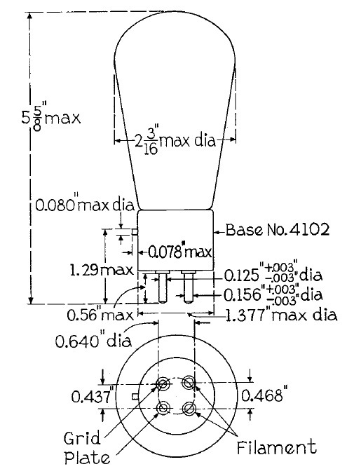
Only a few DHTs have amplification factors which make them suitable to get significant gain. Most of the higher mu ones with an amplification factor in the two digit range have very high plate resistances which limit their usability. The 841 is basically a modified 801 with the grid spacing altered to increase the amplification factor. Dispite it's high mu it has a still moderately low plate resistance of 40 kOhm. Too high for transformer coupling, but perfectly usable with RC coupling. Even LC coupling seems feasable with a suitable plate choke. The 841 has the same UX4 base and pinout as most DHTs. The base connections are pictured on the left. The complete RCA datasheet can be found here. As with most directly heated tubes, the preferred mounting position is up right with the base down. The RCA datasheet allows horizontal mounting if the plane of the electrodes is vertical. This avoids shorting of the filament to the grid. The filaments are quite flexible and can sag a little when mounted horizontally. Keeping the electrode plane vertical avoids the hazard of a short. Still I prefer to mount all DHTs up right. The 841 was manufactured by various of the large tube companies. The military designation of the tube is VT-51.
 
The tube has the same size as the 801A or 2A3. Dimensions can be found in the illustration on the right. As mentioned, the high amplification factor opens the possibility to use this tube in preamps. I actually plan to use it an a phonostage. Most likely with a plate choke and DC coupled to a 801A which will be transformer coupled for low output impedance. The 841 could also be used as a driver tube for DHTs which are easy to drive like the 801A or 45. This would enable a two stage all DHT power amp without the need of a step up input transformer to get sufficient gain. I have not used it this way yet but this is another project for the future. One of the most important aspects of the usability of a tube for audio amplifiers is it's linearity. The plate curves of the RCA datasheet look promising:


The curves from the GE datasheet:


How do these curves match to the reality? Let's have a look at the actual curves taken with a curve tracer:


This looks quite linear to me. So based on the electrical data this tube appears perfectly usable for audio. Another concern, especially in preamps, is microphonics. The further upstream in the signal path a tube is used, the more critical are microphonics. I have done a lot of experiments with DHTs in preamps already. With 801s I found those with ceramic base and graphite plates the least microphonic. So for phono stage use this french 841 from Mazdaradio seems very promising:


Some close up shots of this tube:


Next a VT51 from Hytron:


Initially the 841/VT51 was also made with globe shaped glass before the manufacturers moved to the more modern ST-shape. Like many tube enthusiasts I like the appearance of the older globe shapes. Many people including myself also prefer the sound of globe shaped tubes. Although they can be more microphonic as those with shoulder type glass, they seem to be worth it. A reason for the increased microphonics of globes is the lack of mechanical support of the electrodes on the top. The ST shape was introduced to provide extra support through a sheet of mica which stabilizes the tube structures. But the lack of that mica in the globe tubes might be a reason for their better sound since the mica can release some gas during the life time of the tube. In fact I found most globe tubes to have excellent vacuum dispite their age. A beautiful Taylor globe 841:


Some close up photos:


Next photos of a stunning globe 841 from General Electric:


And some close ups:


It has become a tradition of the Tube of the Month series, to dissect a tube and to have a close look at the internal construction. Luckily I had a dead 841 to take appart. First the glass needs to be removed:


The filament tension springs:


The grid structure:


A closer look:


A comparison between the grid of a 801A (top) and a 841 (bottom):


The tighter grid spacing is responsible for the higher amplification factor.
 
A very promising tube! Stay tuned for updates about it's use in an upcoming phono stage!
 
Best regards
 
Thomas