DISCLAIMER

All rights of photos and text reserved. Usage of photos or text from my blog on other websites or for any other purpose only with prior permission. If you want to use any material from my blog please contact me by email.

Thursday, November 29, 2012

The Modular Preamplifier, Part 12: DHT Gain Stage - Circuit and Initial Construction Steps

Hi!

Earlier this year, I already introduced the modular preamplifier concept. Here a post about the first modular phonostage in this style. The phono got broken up into input and output gain stages and separate MC step up and EQ units to be able to experiment with different gain modules. One of the ideas behind this was to experiment with directly heated triodes in the phono section. As a first step the phono output stage can be changed to DHT. And later maybe the input stage as well, but the usually high mircrophonics of DHTs might prevent this.


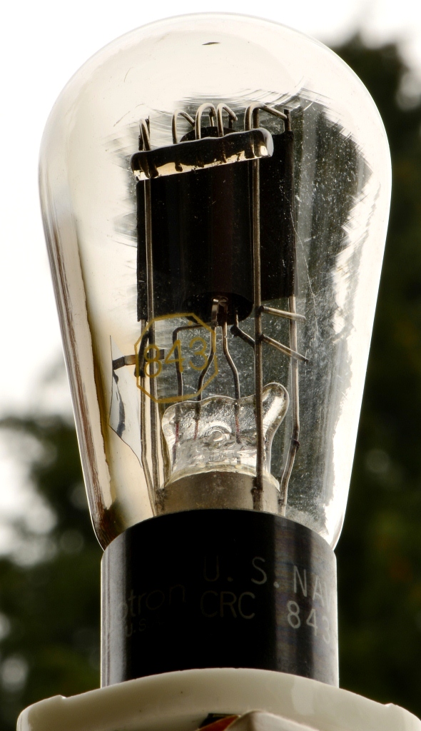
The first circuit draft of a directly heated gain stage is shown above. The plan is to use the 841 as the gain element, because it is one of the few DHTs with considerably high amplifaciotn factor. Since it has a rather high plate resistance, it will be choke loaded and DC coupled to a 801 which will drive a step down line output transformer for low output impedance. To minimize capacitors in the signal path, the 841 will use filament bias. The output stage uses an ultra path cap from B+ to cathode (filament) of the 801. The other caps are there for decoupling and are not directly in the signal path. The 841 will run at about 5mA. Since the 801 operates at a higher current, a bypass resistor of about 47k is needed for the current difference. Final values need to be checked and if necessary adjusted once the circuit is built.

The power supplies will follow my usual approach with passive choke filtering and tube rectification. Since this is meant for phono use, the usual LCL approach for the filaments will not be sufficient, so another LC stage needs to be added which ends up in 3 chokes per tube, 12 total! 8 of these chokes will be placed in the PSU unit and the final chokes in the preamp section. High voltage will be rectified with a TV Damper bridge, followed by LCLCLC filtering and the final LC decoupling separate per channel in the preamp section.

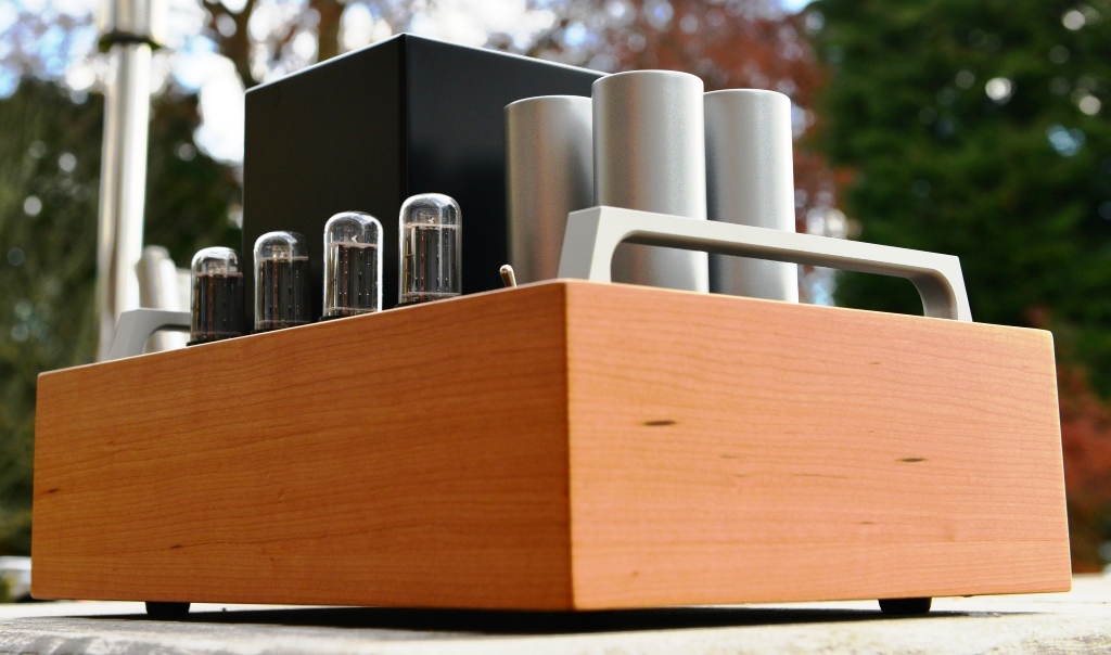
This is a lot of iron, so 3 chassis are needed. Separate PSUs for filament supplies and high voltage. Even with the three chassis, there are too many components to use the enclosed wooden frames, so some parts need to be placed on top, similar to the 10Y preamplifier

The initial construction steps for the filament supply chassis. Power transformers placed on the top:


The filament transformer which is used is described here. Due to the high voltage drop through the chokes, 1 per tube is not enough. 2 more transformers are added. The separate secondaries of those are shared between two supplies.

The initial wiring of the filament transformers:


The filament chokes are mounted on sub plates which will be placed inside the wood chassis:


The rectifier bridges using Schottky diodes are directly soldered to the input choke along with the filter caps:


The high voltage supply will be constructed in a similar style, transformers, input choke and rectifiers placed on top of the chassis:


Since the circuit uses 800V B+, two transformers are needed with the secondaries in series. To keep the heater to cathode voltages for the rectifiers within specs, 3 separate heater windings are required. Since each of the B+ transformers has only one heater winding, a separate heater transformer is added for the third one.

The initial wiring:


And finally the first construction steps of the signal chassis. Sockets mounted on vibration damped sub assemblies. The capacitors are Sprague paper in oil types with 2kV voltage rating. Here painted in white:


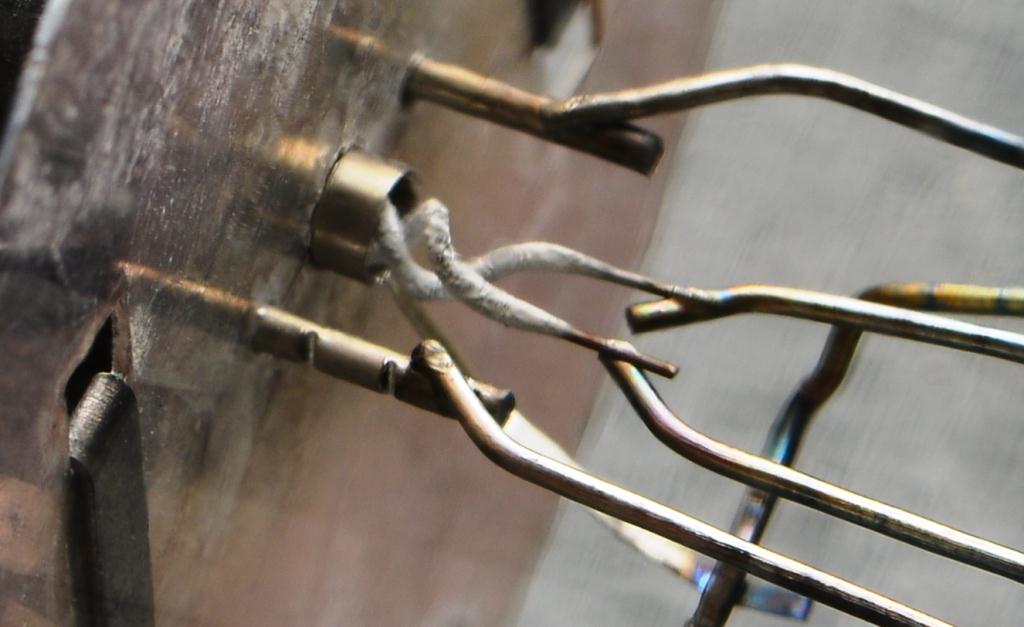
The initial signal wiring:


The filament bias resistors are at the front. The connection between them serves as star ground point. All signal wiring is done with solid core silver wire.

This is probably one of my crazier projects. You might wonder why so much effort and why not try smaller DHTs which need less filament current. And why no regulated supplies instead of those heaps of iron. Such an approach might follow later. First I want to create the ultimate DHT phonostage. And that has to use tubes with thoriated tungsten filaments in my book. While there are good solutions for filament regulators, I still prefer the passive approach. Such regulators work best if preceeded with a good supply with choke input filter anyways, so staying completely passive is not that much more in terms of parts.

Stay tuned for updates as the construction of this DHT gain stage progresses.

Best regards

Thomas


Sunday, November 25, 2012

Making of a 10Y line preamplifier

Hi!

This post will show the assembly process of a 10Y line preamplifer in the classic 'landscape style' chassis. This preamp is meant to be used with the E55L LCR phono stage presented earlier this year. So the same wood, color and chassis design was chosen.


I call this design 'landscape style' to distinguish from my earlier preamp design which is placed with the short side at the front, for example the 801/26 preamp.

As always, the assembly process starts with the metal plates wich carry the whole circuit. The linestage plate:


The switches,  RCA and power supply connectors are aleady attached to the plate as well as the vibration damped sub assemblies with the tube sockets for the 10Y (801A can be used as well).

From below:


The plate of the external power supply:


The plates get mounted into assembly rigs for further construction. The capacitors are mounted. They are clamped onto the plate with aluminum profiles. Inputs are already wired to the selector switch:


In the PSU the sockets of the rectifier bridge of 4 6AX4 TV dampers is wired up and teh caps are mounted with the same technique as in the preamp. Also the power amp is attached to the top side, placed on some rubber damping elements:


Chokes (2 for high voltage and 2 for the filaments), line output transformer and Slage transformer volume controls are mounted on a second level below the metal plate:


In the PSU, filament transformers, filament rectifiers and another 4 chokes mounted on the second tier:


The finished preamp with power supply.


Another view:


4 Inputs and 2 paralleled outputs:


The PSU uses 4 6AX4 TV Dampers in bridge rectifier confoguration (Gratz bridge).
The 6DQ4 can be used as well.


The preamp can operate with all these tube variants: 10, UX210, 10Y, VT25, VT25A, 801, 801A, VT62 and 1602.


Best regards
 
Thomas


Thursday, November 22, 2012

Tube of the Month: The 843

Hi!

The last two Tube of the Month articles covered variants of the 801A with higher and lower mu. This months tube can be considered as an indirectly heated variant. The 843.


The 843 has very similar parameters to the 801. The amplification factor is 7.7 (versus the mu of 8 of the 801) the plate resistance is 4800 Ohms (4600 for the 801). With a max. plate dissipation of 12W it is actually closer to the 10Y than the 801A.

Being indirectly heated it needs one more pin to bring out the cathode connection. Thus it has a UX5 base. The pinout is pictured on the left. Where it differs from the 801 and 10Y is the heater voltage. It requires 2.5V at 2.5A. Please see the datasheet for all details. With an adaption of the socket and heater voltage this could be an interesting alternative to the 10. While the 10 or 801A require well filtered filament supplies for hum free operation, this tube could be used with AC heaters. It could be interesting as output tube or driver tube and potentially a preamp tube as well. I have not tried the tube myself yet.

As usual, let's have a look at the plate curves to see how linear it is. These are the curves from the datasheet:


The curves in the datasheet are a bit skewed since they also cover the Class A2 operating area with grid current. Linearity of the Class A1 region is difficult to judge. So let's have a look at the curves taken from an actual tube with the curve tracer:


This looks very promising! Definitely a tube which can be considered for audio purposes. It seems that it is not widely used among amplifier builders.

The 843 was initially made in globe shape and later also with the more modern ST (shoulder type) glass:


Let's have a closer look, first the ST type:


 Some close up shots of the plate structure:


As with all ST tubes, mica discs are used to align the internal electrodes.


The next photo shows the indirectly heated cathode.


The tube lit up:


A close up of the heater:


A beautiful tube! But the globe is even prettier:


Let's have a closer look to this one as well:


As is typical for early globe tubes, no mica is used. The elctrode alignment is done with a piece of glass inside the tube:


A closer look at the cathode, here from the top side:


And from the bottom:


The heater lit up:


From the top, this photo shows the grid around the cathode sleeve:


This is the last post about tubes from the 800 series for now. There are more interesting 800 tubes which will be covered in the future, but first we will have a look at a completely different kind of tube in next months post.


Best regards
 
Thomas