DISCLAIMER

All rights of photos and text reserved. Usage of photos or text from my blog on other websites or for any other purpose only with prior permission. If you want to use any material from my blog please contact me by email.

Tuesday, March 15, 2011

Music: Jimmy Giuffre, Tangents in Jazz

Hi!

In this second article about my favorite music, I'd like to write about Jimmy Giuffre. I pretty much like all his records. But one of them is quite remarkable since he is going new, different ways: Tangents in Jazz


A very early album from him, released 1955 on Capitol. This album is quite experimental. What is so unusal about it is the absence of an explicit beat. Although the quartett has a bass and a percussion set, these do not provide the rythm or beat as usual. The entire album provides full attention to the notes and phrases and the percussion and bass participate in this.

Even with the absence of an explicitly played beat, the music has drive and rythm. Quite fascinating.

Being recorded in 1955 this album is from the era before stereo. Dispite the fairly early recording date the technical sound quality is excellent. No hiss, a lot of detail and natural dynamics. Uncompressed and unprocessed pure sound! Stereo addicts will be fascinated by the depth of this mono recoding. The instruments have real body. And best of all those beautiful sound colors! A masterpiece in terms of technical recording, innovative music style and passionate playing. This record draws you in. It is playing right now, while I write this article.
I like such experimental music which goes different ways. I'll present two more recordings in future articles which experiment with the way the rythm is done.

Best regards

Thomas

Saturday, March 12, 2011

Making of a 211 Amplifier, Part 1: Planning

Hi!

Ever since I started building tube amplifiers, the 211 was among my favorite tubes. In fact the very first power amp which I built used the 211 as an output tube. This first amp evolved through several stages and finally ended up in huge monoblocks with 211 drivers and even bigger 3 phase power supplies. Those of you who are familiar with the Sound Practices magazine might have read my articles about this amp and the 3 phase power supplies.

After I started to go commercial with my amplifier designs, I decided to build a scaled down version of this amp. It used a single phase supply, and a smaller but still directly heated driver, the 801A. Power supplies were still external so that the whole amplifer ended up in 4 chassis and has a weight of more than 100kg.

This is a photo of one channel of the amp:


Tango interstage and output transformers, NOS paper in oil caps in the power supply. DC heating for both driver and output tube using a purely passive LCL filter per tube. The sound of this amp is excellent and very close to that of the bigger one with 211 driver. The amp was publicly demonstrated at the ETF 2009 in Stella, France. Yet for many the sheer size of this amp with 4 chassis in total is a bit overwhelming. Here is a photo of the complete set:


The 4 chassis in the front row are just one stereo amp!

Also the cost of such a 4 chassis beast is quite high. The use of the finest Tango transformers contribute a good part to the overall cost. Also quite significant the expense of 4 chassis. Since the 211 is operated at max B+ voltage, very high quality umbilicals and PSU connectors need to be used which are rated for the voltage, again a cost driver. Yet the 211 and 845 tubes are quite popular and many people need more power than can be obtained from smaller tubes. So the idea for a yet further scaled down 211 came up. The actual development of a smaller version was triggered when Lundahl announced the availability of a new output transformer with a high 20k primary impedance, the LL1691B. Twice the primary impedance of the 10k which is commonly used in 211 designs. This should ensure a more linear operation of the output tube and provide a lower output impedance.

As mentioned above a big cost driver are the 4 chassis. Also the elaborate power supply with choke input filtered B+ and separate DC supplies for output and driver tubes. Some simplification is necessary there. Of course a good way to make the amp simpler is the use of an indirectly heated driver. Possibly a similar architecture as presented in the single ended amplifier concept series. This means a two stage approach. While this is fairly easy with smaller triodes, it is more of a challenge for a 211 if the same level of gain and headroom shall be reached.

Since I already had good experience with the 6HS5/6HV5A family of tubes as output triodes (this will be coverd in upcoming articles) I always wanted to use them as drivers too. They have an extremely high amplification factor of 300. Their plate resistance is still in a range which enables transformer coupling. See the datasheet for details. The amplification factor is even high enough so that the interstage transformer can be wired as step down. This should give a nice low impedance driver which even allows the 211 to be pushed into Class A2 territory. A suitable interstage transformer can also be found in Lundahls portfolio, the LL1660/25mA. Even if the interstage is wired in 4.5:1 the overall gain is still enough so that no input transformer is needed as with the 801A/211 or 211/211 versions. This makes the design more widely usable with almost any preamplifier.

Normally the high plate voltage requirement of the 6HS5/6HV5A is a disadvantage but since we already have B+ in the range of 1300V for the 211, the supply voltage for the driver can be derived from the 211 output stage B+ via a separate LC decoupling stage. This further simplifies the amp.

No compromise should be made in terms of capacitor quality, so no electrolytics in the B+. Also the amps should be as hum free as possible, which makes DC filament supplies necessary for the output tubes. Since the DC filament supply has a massive impact on the sound quality, no other approach than the well proven passive LCL filter is considered.
As mentioned above, a big cost driver is also the choke input supply for the B+. Especially at these high voltages very massive input chokes are needed since they have to withstand a large AC voltage amplitude across them. Therefore another approach will be used. A voltage doubler supply, but with tube rectification. This enables the use of an existing power transformer, the 400mA universal B+ transformer as was shown in my article about power transformers. Since the driver tube has a compactron base, a TV damper with the same will be used for the rectifiers, the 6CG3. The 6CG3 is one of the strongest TV damper tubes. It is capable of 350mA DC each. In a bridge configuration two of these can deliver 700mA! In a voltage doubler arrangement, each rectifier has to deliver the full current which is consumed by the load, still the theoretical maximum of 350mA which two 6CG3s can deliver in a voltage doubler is more than adequate for a mono amp.

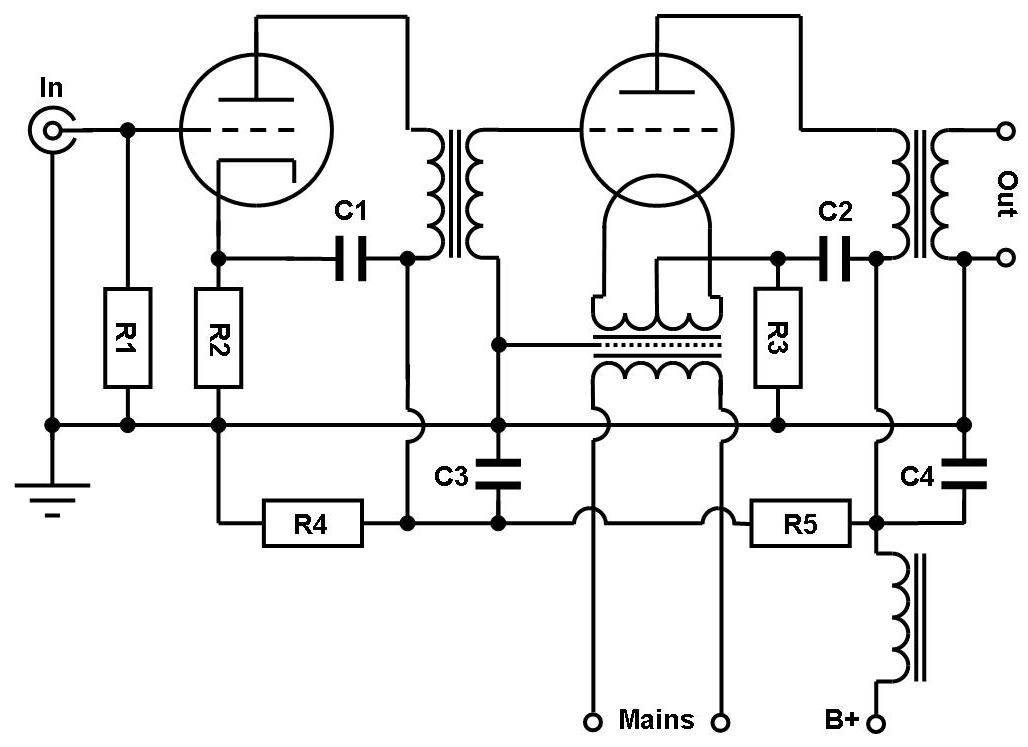
This leads to a design which is outlined in the schematic below:


Although this is a 'scaled down' amp it is still a beast, 4 transformers (output, interstage, B+ and filament) 5 chokes (2 filament, 3 B+) and a large array of paper in oil caps per channel. For the oil caps the same 5uF/2kV types as in the 4 chassis amp will be used. Each 10uF cap value in the schematic will be done with two of them in parallel. No way all these parts would fit into one chassis for a stereo amplifier. The concept will be built up as mono blocks.

In the second part the assembly process will be shown. Stay tuned.

Best regards

Thomas


Wednesday, March 9, 2011

Tube of the Month: The 6AX4

Hi!

As you could already read in previous articles, I prefer TV damper tubes for rectification. My favorite among those is the 6AX4.


The use of TV dampers in power supplies was advocated by JC Morrison in Sound Practices magazine back in the 1990ies. He mostly uses them as a slow turn on device in conjunction with silicon rectifier bridges. TV dampers have been developed for TV service. Their purpose was to dampen oszillations in the deflection system during the fly back period of the electron beam. This requires a very tough diode which can handle very high peak inverse voltages and peak currents. These properties made them perfectly suited for mains rectification as well. However this was not promoted by tube manufactures since they wanted to continue to sell their dedicated rectifier tubes, which where more expensive. There is still a prejudice against TV dampers as rectifiers because of this. Many years of experience with TV dampers in various power supplies proofed that they are extremely reliable and perfectly usable as rectifiers. Another advantage is their extremely low cost.

The 6AX4 shares the same base diagram with other similar types like 6DE4, 6DM4, 6AU4 and many others. It is also available with different heater voltages and for series heater connection as types 12AX4, 17AX4 and 25AX4. A detailed datasheet can be found here. The 6AX4's current rating is on the low side compared to some of the other TV dampers. So why did I chose it as my favorite? The current rating is still way beyond the needs of most amps I build. More than enough to power both channels of a SE power amp. When followed by a choke input filter, a 6AX4 rectifier bridge can deliver more than 300mA continous. The advantage of the 6AX4 is it's lower heater current compared to others. It needs only 1.2A. When 4 of them are used in a bridge, the higher heater current of other types can become a difficulty. Therefor I stick with the 6AX4 for most applications. If higher current is required, I use some of the beefier TV dampers. Another big plus of TV dampers is their good insulation between heater and cathode. Please note that this voltage is quite different depending on the polarity. The cathode can be at substantial higher voltage than the heater, while they don't like the heaters to be too postive against the cathode. For the 6AX4 the cathode can be up to 900V DC above the heater potential. This means that all heaters of the 6AX4s in a Greatz rectifier bridge can be wired in parallel and fed from a secondary winding which is referenced to ground. This is safe for power supplies with choke input filters which deliver up to approximately 650VDC. Higher voltage power supplies like those for 211 amps will require at least 3 different heater windings for a rectifier bridge to ensure cathode to heater voltage is not exceeded. The schematic below illustrates how the heaters need to be supplied and biased in the case of higher voltage PSUs:


The 6AX4 was available from almost any tube manufacturer. Although production of this tube has ceased a long time ago, it is still available in large numbers. Below is a selection of 6AX4 tube boxes of different brands:


The 6AX4 was made in various forms, most with the common large Octal base, in later years it was also broduced with the flat 'coin base':


The last photo shows a 6AX4 Graetz bridge in a power supply:


Best regards

Thomas

Friday, March 4, 2011

Making of a 45 / 2A3 amplifier, Part 2 - The PSU

Hi!

This article shows the assembly process of the power supply unit of the 45/2A3 amplifer which was presented in an earlier post.


The photo above shows the completed Power Supply.


The series of pictures on the left illustrates the assembly process of the PSU step by step.

The first photo shows the metal plate which holds all components. It is mounted into an assembly frame. On/Off switch, sockets, B+ power transformer, B+ filter caps are already mounted on the palte as well as fuse holder, connectors for mains and the umbilical.

The second photo shows the under side of the plate. Here it can be seen how the caps are fixed. Some initial wiring is already done: Heaters of the rectifier bridge (Graetz) which uses 4 6AX4 TV Damper tubes. Also the high voltage AC from the power transformer to the bridge is already done.

All other components are mounted on a frame of aluminum profiles on a second tier. In the third photo the chokes and filament transformers are mounted. One filament transformer for each of the driver tubes (switchable between 26 and 10Y or 801A).

B+ is smoothed via a choke input filter with two LC sections. Filament supplies are LCL filtered. The first LC section is placed in the PSU, so 2 filament chokes, one for each channel.

The last photo on the left shows the completed wiring of the inside of the PSU. Rectifier bridges for the filament supplies have been added, using Schottky diodes. Each filament choke is followed by 40.000uF smoothing capacitance. 4 10.000uF caps are wired up in parallel on each side.

The PSU is ready to be fired up and tested. The sound of this all DHT amp is fantastic. The 26 complements the 45 very well. Depending on taste or mood, the driver can be exchanged for the thoriated tungsten filament 10Y / 801A family tubes which give increased resolution, especially in the treble. This amp is supposed to be used in an active 2 way set up. It will power a midrange / treble horn. But the amp can be used full range as well. Currently no input transformer is added. This way the amp has very low voltage gain (about 0dB). This fits perfectly to a 2-way system with an highly efficient horn and less efficient bass. Not much level adaption to the bass is necessary, just some minor fine trim in the crossover between preamp and power amps.

Below a picture of the amp and power supply together. The amp is equipped with ST shape 45 and 26 tubes:


Two more fotos, this time with globe shape tubes UX245 and UX226:


Best regards

Thomas

Tuesday, March 1, 2011

Single Ended Amplifier Concept, Part 6

Hi!

All the previous posts in this series showed indirectly heated tubes in the output stage. Today we will see how the same concept can be applied to directly heated tubes as well:


This is a generic schematic which shows how this can be adapted to DHTs like 45, 2A3, 300B, etc. The driver stage can stay the same as in the 6CB5A version. The main point which is different is the cathode of the output tube which is now directly heated, that means the filament itself becomes the cathode and thus is in the signal path. So it needs to be handled with some care. DHTs can be heated with AC or with DC. The schematic shows AC heating which is the simplest form and can easily be done such that the filament supply has no negative impact on the sound. This is much more difficult in the case of DC heating and will be covered in a later post.

AC heated DHTs have one draw back: There will be some remaining hum. Often hum bucking pots are seen in these cases. However we want to avoid such an ugly pot right in the signal path. This requires a filament transformer which has center tapped windings. This center tap becomes the cathode connection of the tube and is hooked up to the cathode bias resistor. It is also the connection point for the ultrapath capacitor (C2).
This method does not allow any hum adjustment and relies on symmetry of the filament winding and the filament itself. Hum level can vary a bit from tube to tube. Very well suited for this scheme are the 2.5V filament types like the 45 or 2A3. Residual hum will be negligible with these. With 300Bs, hum level could become too much with this scheme as they are heated with 5V. I personally prefer DC heating for 300Bs for this reason. With 45s and 2A3s I stick to the AC scheme as pictured.

As mentioned already, the filament supply is very critical. Any noise present here will be injected into the signal. For this reason the filament transformer should be of high quality and have a screen between primary and secondary sides. As usual I even use transformers with two screens. The filaments should be supplied from a separate transformer. The filament windings should not be on the same core as the B+ windings. This avoids any switching noise from the B+ rectifier to be injected into the filament circuit. In a stereo amp, both windings for the two channels can be on the same transformer. Even if the power supply of the amp is separated into an external chassis, the filament transformer for the output tubes should stay in the amplifier section, close to the output tubes.

The rest of the schematic is the same as shown in previous posts. The interstage transformer needs to fit to the driver tube. Again the 6N7 works nicely with a LL1660/10mA driving small DHTs like 45 or 2A3. For the 300B it is advisable to use the beefier 6J5 instead of the 6N7. The output transformer also needs to be matched to the tube used. For example a Tango XE20S, configured for 5k primary for the 45. Also the Lundahl LL1663 would work nicely.

C1 and C2 are the ultrapath capacitors as has been described in previous posts. C3 is the B+ decoupling cap of the driver stage. C4 decouples the output stage separately for each channel. R1 is the grid to ground resistor of the input tube and also sets the input impedance of the amp. Values of 100kOhm or 200kOhm are suitable. R2 is the cathode resistor of the input tube which sets it's operating point. In case of the 6N7, 1kOhm is a good value. A 1W rating is sufficient here. R3 is the cathode bias resistor of the output tube. In case of the 45 1.5kOhm/5W would be suitable. It needs to be chosen correctly for other DHTs. In both cases trials with and without cathode bypass capacitors can be made. Depending on the plate resistance of the tubes and the size of the ultrapath cap, a bypass cap can be necessary to avoid early low frequency roll off. A good starting point would be 25-30uF for all the caps shown in the schematic.

The choke decouples the two channels from each other and from the power supply which can be common to both. The current rating of the choke needs to be sufficient, depending on the current draw of the tubes. R5 decouples the driver B+ from the output tube. It needs to be set according to tube choice. R4 forms a voltage divider with R5 and also acts as a bleeder resistor. B+ and the value of these resistors depends on the voltage requirement of the tube chosen. For example a 45 would require around 300V B+.

Of course the same RC coupled driver stage which was shown as a lower cost alternative in an earlier post, can be used with a DHT as well. The same type power supply as shown before can be used. The voltages need to be adapted accordingly.


The photo above shows a 45 amp with external PSU based on this concept. The amp is equipped with globe UX245 tubes. The next photo shows another implementation. This one can accept both 45 or 2A3s as output tubes. The correct operating point for each is chosen by a switch which seloects the appropriate cathode resistance:


In future installments of this series we will see how this concept looks like with DC heated filaments and how this can be modified for an all directly heated amp with tubes like 26 or 10Y in the driver stage.

Best regards

Thomas