DISCLAIMER

All rights of photos and text reserved. Usage of photos or text from my blog on other websites or for any other purpose only with prior permission. If you want to use any material from my blog please contact me by email.

Sunday, June 17, 2012

Making of a SE 6CB5A Amplifier: Assembly

Hi!

In this article, the assembly process of the SE 6CB5A amp will be shown.


First the metal plate which holds all the parts gets mounted in an assembly rig:


Here the caps, power transformer and tube sockets are already mounted. Some initial wiring to the power transformer and rectifier sockets is done:


Heater wiring to the signal tubes and some wiring to the caps:


Output transformers, two of the chokes and the resistors mounted and wired up:


The last missing pieces, interstage transformers and two more filter chokes:


Everything assembled and ready for the first measurements and listening test:


After measurements and listening test results are as expected, the power transformer cover can be mounted and the amp inserted into it's wooden frame:


Another shot taken in the dark, with the amp switched on:


The assembly of the matching line stage is almost finished and will be shown in an upcoming article.


Best regards

Thomas

Thursday, June 14, 2012

Tube Box Art, Part 7: Various Brands

Hi!

Todays Tube Box Art article will cover various brands. These are less know. Some of them private labels or rebrands from major manufacturers.


Let's start with some close ups of a brand called Gold Coast:


This was a private label of a department store who rebranded tubes they sold.


Wouldn't that be great if you could still walk into a department store and buy such tubes?


Next are two different boxes of Majestic:


Majestic was a manufacturer of radios. Not sure if they made their own tubes or if they rebranded from others.


The right box of a G-37 contained a Cunninghamm 337. But that doesn't mean that this tube was in there originally. Often when tubes got replaced in a radio set, the old tubes got kept in the boxes of the replacement tubes.


Next is a box with a marathon runner as motif, which matches the brand name:


The Marathon name was most likely chosen to imply durability. The box contained a rectifier, matching the rectifier tube print on the box. But strangly there is a MX250 designation on the bottom of one side. On the top flap there is a stamp above that which mathes the tube it contains:


A box of the brand Triotron:


Another 281 rectifier tube box from a comapny called United, not to be confused with United Electric:


As the imprint on the side says this is probably a tube manufactured by RCA:


The tube in the box had no markings at all.

The box showed the basic specs of the tube, very convenient:


The top flap:


Next is the box of a UY227 indirectly heated triode from  Sonatron Tube Co, a less known manufacturer of vacuum tubes.


Again the tube specs are printed on one side of the box:


The top flap:


I have a few of these Sonatron UY227s. Interestingly they seem to be from some sort of life time test as this notice implies:


The tubes contained in these boxes still measure well!

And as a last goodie I'd like to share photos of a box of UX201A triodes from a brand called Gold Seal:


These Photos of the Gold Seal tube were kindly provided by a reader of my blog.


Many thanks to Milan, for sharing these pictures!

Best regards

Thomas

Sunday, June 10, 2012

Making of a 6AH4 line stage: circuit

Hi!

In the previous article the 6AH4 linestage was mentioned, which is meant to be used with the 6CB5A amp. As with the power amp, I will describe circuit and assembly process of the line stage in two separate articles.


The linestage shares the same circuit with the two chassis version which was already presented. Only this time power supply and preamp will be in one housing which will be in the same style as the power amp it is supposed to drive. The circuit is basically the linestage section of my Octal preamplifier Mk2. The only difference is in the heater supply, which can be AC since this is a linelevel preamp only.

The picture below shows the complete schematic with both channels and the power supply:


The TVCs are done with 24*2 db/step autoformer modules from intactaudio. Volume control and input select switches are swiss made from Elma. All capacitors are ASC MP in oil types. No electrolytics.

The only amplifying element is a 6AH4GT triode per channel. This is a low mu triode with low plate resistance. With the 3.5:1 step down this yields a very low output impedance, more than suitable to drive a TVC and long cables to the power amp.


As in the 6CB5 amp, a hybrid rectifier bridge was chosen. UF4007 diodes complement the 6AX4 TV dampers. Two diodes are in series in each leg, since substantial peak inverse voltages can occur in a choke input filter supply. The power transformer is of the same type as the one used in the power amp. Only a smaller version since the preamp has much less current draw. The power transformer has grain oriented core laminations and dual electrostratic screens between primary and secondaries. In addition there is a flux band around the outside of the winding stack.

The output is basically floating to allow differential connection to the power amp. One side is connected to ground through a 1M resistor to avoid static charge build up in the output which could cause a plop when plugged in while power amp is turned on. The heater supply of the 6AH4 is referenced to ground through 2 100 Ohm resistors.

The preamp has the same ground lift option as the power amp to allow adjustment to any grounding situation in the system.

The construction will be done on the same style metal plates as for the power amp:


Stay tuned for the second part which will show the assembly process.


Best regards

Thomas

Thursday, June 7, 2012

Making of a SE 6CB5A amplifier: circuit

Hi!

I was recently asked to build a line stage and power amp for someone. The request was for single chassis designs at reasonable cost which would still offer outstanding sound quality. The natural choice for that is a design which does not use any of the overly hyped and expensive tubes, so I proposed a SE 6CB5A amp.


The 6CB5A still is among the most underrated tubes. I chose a similar circuit as already discussded in this single ended amplifier concept article. With some minor changes. Instead of the Lundahl LL1663 or LL1664 I decided to use the LL1682/70ma as output transformer. This transformer has a slightly higher primary impedance and a 5 Ohm secondary. This makes the amplifier usable with a wider range of speakers. It has a better damping factor for good low frequency control at a minor loss in maximum output power. As in the original design the LL1660 interstage transformer is used.

Here is the complete schematic of the new design, showing both channels which share a common power supply:


There are also some changes to the original power supply design. As in almost all my recent power suppies, I opted for a full wave Graetz bridge rectifier scheme. Since everything is supposed to fit into a single chassis, the available space for tube sockets is limited. Therefor the decision was to go for a hybrid bridge. Two 6AX4 TV damper tubes for the upper part of the bridge supplying the B+ and UF1007 low noise silicon diodes for the ground legs. Separate filter chokes provide isolation between the channels to avoid any interaction through the common supply.

As in all my designs, a ground lift switch is used for convenience. This offers the possibility to break ground loops in case the signal ground is connected to earth in several places in the system. Of course all metal parts are always connected to safety earth, no matter if signal ground is lifted or not.

The amp will be constrcted in my 'classic' style, everything mounted on a metal plate which will be inserted into a wooden frame. The metal plate is already manufactured:


The back side of the plate:


The detailed construction will be covered in a second article.


A 6AH4 line stage is the perfect preamp for the SE 6CB5A. Circuit and assembly of the linestage will also be shown in separate posts. Stay tuned!


Best regards

Thomas

Sunday, June 3, 2012

The Modular Preamplifier, Part 11: 10Y linestage

Hi!

In a previous post I already showed the chassis design of the 10Y linestage. Now it is finished, including power supply.


The power supply comes in the same chassis style:


Under the transformer covers of the PSU there are 2 filament transformers (one for each 10Y), the B+ transformer and the first choke of the LCLC choke input filter. The chokes of the filament supplies, the second B+ choke, smoothing caps and all the rest are mounted inside the chassis:


The preamp chassis is filled inside with separate B+ filter chokes for each channel and two filament chokes feeding the 10Ys.


Initial listening test is very positive. The Tribute output transformers with volume control secondary work nicely. They also measure well across all volume settings.


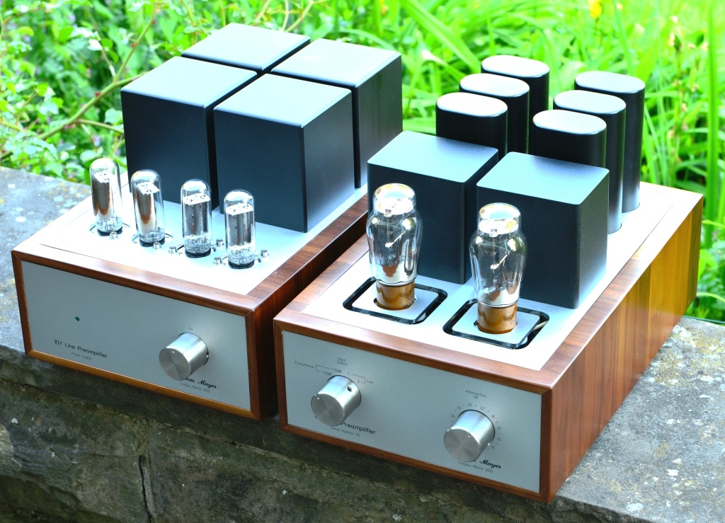
The linestage together with the E55L phonostage:


Quite a massive preamp with it's six chassis. If MC step up transformer and LCR EQ are chosen with their own chassis, there are even eight of them:


The line stage and it's PSU in operation:


More listening tests will follow.

Best regards

Thomas