
I have been working on a complete amplification chain containing phono stage, line stage and mono amps during most of the last month. They will all share the same chassis style as my 10Y line stage. Each with external PSU, so 8 chassis total. I will show all of them in dedicated posts. This first post shows the current state of the D3a phono stage.

I already announced this phono stage in the D3a Tube of the Month article. The circuit topology is described there. The reason for the choice of the D3a is the higher amplification this tube can yield in an LCR phono stage compared to an E55L for example. The person who will use these electronics has a very low output cartridge. So every bit of gain is needed.
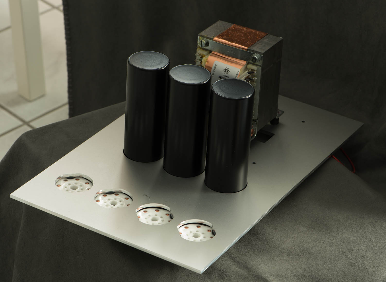
As already shown in previous posts about preamps, each socket is mounted on a small sub plate which is vibration damped through rubber pieces. Here a top view of the main mounting plate which will later be exposed on the top of the chassis:

The underside of the plate showing the signal and heater wiring:

Two of the 4 B+ decoupling chokes used in the circuit are hidden under the two black covers in the middle. The remaining chokes and transformers will be placed inside the chassis:

Both stages of the circuit use Lundahl LL1692A transformers. The 600 Ohm LCR RIAA is built discretely, using intactaudio RIAA coils:

The reason for the use of discrete LCR networks was the wish for the inclusion of the Neumann time constant. The second half of the network got modified such that the attenuation of the high frequencies stops around 50kHz.
Another requirement was the use of XLR in and outputs wired in parallel with RCA connectors:

The backside also carries separate binding posts for signal ground and chassis, the power supply connector and a ground lift switch. The back plate is prewired as far as possible before it is mounted to the preamp:

The PSU is constructed in a similar style, the top plate:
The power transformer will late be hidden under a black cover. The wiring underneath:


The front and backside panels of the PSU:

Now only the wooden chassis are missing. As soon as these arrive, the phono stage will be completed. This will be covered in part 2.
Best regards
Thomas
Great!
ReplyDeleteCan we see schematic?
I tried to find everywhere but with no success :(
Hi!
ReplyDeleteThis phono stage is available as a kit or partial kit. Schematics will be provided with the purchase of parts. Gotta keep at least some secrets ;-)
Thomas
1A 1A
ReplyDeletedear Thomas,
ReplyDeletecould you please let us know the strategic parts you can supply for this phono ?
best regards,
Pedro
alicante(costa blanca
Hi Pedro,
ReplyDeleteI can supply everything needed for this preamp.
The important parts are the signal transformers and LCR coils.
Also the power supply chokes and I believe the power transformers are very important.
I can also provide the capacitors.
You can also get a subset of parts for example if you have a specific preference for caps and want to use others or if you have a LCR network already.
Schematics will be provided also with a subset of the parts. I will also be available for consulting during the construction in case of any questions.
Contact me be email: thomas -at- vinylsavor -dot- de
Best regards
Thomas
Thomas,
ReplyDeleteHave you tried the Lundahl LCR Inductors?
Yes I did, but prefer the intactaudio coils
DeleteThere is a beauty coming up :-)
ReplyDeleteVery nice, Thomas!
ReplyDeleteI wonder what rubber parts are you using to decouple the small tube plates? I noticed you use thicker solid core wires for ground for the tubes. Will these thick wires decrease isolation of the tubes?
I like very much that no screws are visible from the top due to use of the blind tapped holes. What thickness of the top plates are you able to get away with? 5mm?
Regards,
Tony
Hi Tony,
ReplyDeleteThe rubber elements are from a local supplier. The impact of the ground wire on damping is minimal. If the sub plates damping is too soft, it is not effective in absorbing vibrations.
The plates are 4mm thick
Best regards
Thomas
Thanks, Thomas.
ReplyDeleteAt first I thought you are using O-Rings but I noticed it is a single rubber element. It is pretty good machining of blind holes if you can only use a 4mm plate.
Regards,
Tony
Hi Thomas, I'm building something similar, :-) Did you find any need to screen the inductors?
ReplyDeleteThanks,
Pete
Hi Pete,
ReplyDeleteno screening necessary. This phono is very quiet even if used with a MC cartridge without MC step up transformer. Just keep enough distance to the PSU. half a meter is enough.
Thomas
Thanks Thomas, much appreciated, that makes me more confident that mine should be ok!
DeleteBeautiful build, BTW, I love your style.
Cheers,
Pete
Hello Thomas.
ReplyDeleteLooking at the layout of this D3A LCR phono preamp, it appears that perhaps you are using a combination of the classic Ultrapath circuit, and a high value electrolytic capacitor across the cathode resistor from each of the D3A cathodes to ground. I assume the electrolytic is to suppress what would otherwise be a substantial issue with power supply ripple (hum) in this circuit, even with a well-filtered power supply, being that the D3A is are relatively high-mu tube, and they will amplify the ripple by mu+1. Are my assumptions correct?
If so, have you perhaps tried LED bias with these tubes in this LCR phono preamp circuit? LEDs may be good candidates for this particular application; approximately 20 Ma cathode current per tube, and a low cathode bias voltage of around 1.7 VDC or so. The use of the LEDs would of course eliminate any need to bypass the cathode resistors with a capacitor, etc.
What are your thoughts on this?
Hi!
DeleteThis is an old version of my pono design which I changed substantially in 2015. I am not using LED bias but you can of course try it and see how it works for you
Hi Thomas,
DeleteThank you for your reply!
How did you change and improve the electrical design in 2015, with regard to the biasing scheme for the D3As? How are you now biasing the D3As? And are you still using the Ultrapath topology in this LCR EQ phono preamp?
Thanks in advance!
I am sorry but that circuit is not public. Why does it matter anyways? Why don't you try the idea you wrote above and see how it works for you
DeleteThomas, I completely understand.
DeleteI am building a very similar LCR EQ phono preamp, and yes, I intend to use it as the basis for testing certain variations, etc., of the circuit.
All the Best!